Method and device for eliminating image speckles in scanning laser image projection

a laser image and laser beam technology, applied in projectors, color televisions, television systems, etc., can solve the problems of interference, strong additional intensity modulation of the brightness distribution of the image screen, and the disappearance of the advantages of laser radiation

Inactive Publication Date: 2002-04-09
EADS DEUT GMBH
View PDF10 Cites 47 Cited by
  • Summary
  • Abstract
  • Description
  • Claims
  • Application Information

AI Technical Summary

Problems solved by technology

When using lasers for the illumination or image display on a projection surface, interferences occur due to the roughness of the surface in the space in front of the projection surface due to transit time differences of the waves that emanate from different portions of the projection surface.
These interferences lead to a strong additional intensity modulation of the brightness distribution of the image screen in the eye of the viewer.
As far as we know there are no methods known at this time for the reduction or even elimination of laser speckles in laser beam projection systems which do not simultaneously diminish the image quality to such an extent that the advantages of the laser radiation disappears or that its use hardly brings any technical or economic advantages.
The methods for destroying the localized coherence lead to a very strong beam degradation.
The known methods for the destruction of the time coherence generally only result in a very limited increase of the emission band width and the resulting coherence length is still larger than the largest distance differences from the edges of a projected pixel to the viewer.
The use of the shortest laser impulses (under 1 ps) for the reduction of the coherence length of the laser and thus the diminishing of the interference capability of the light is burdened with an enormous technical effort and expense.
However, moving larger screens is cumbersome and expensive.

Method used


Image

  • Method and device for eliminating image speckles in scanning laser image projection
  • Method and device for eliminating image speckles in scanning laser image projection
  • Method and device for eliminating image speckles in scanning laser image projection

Examples


Embodiment Construction

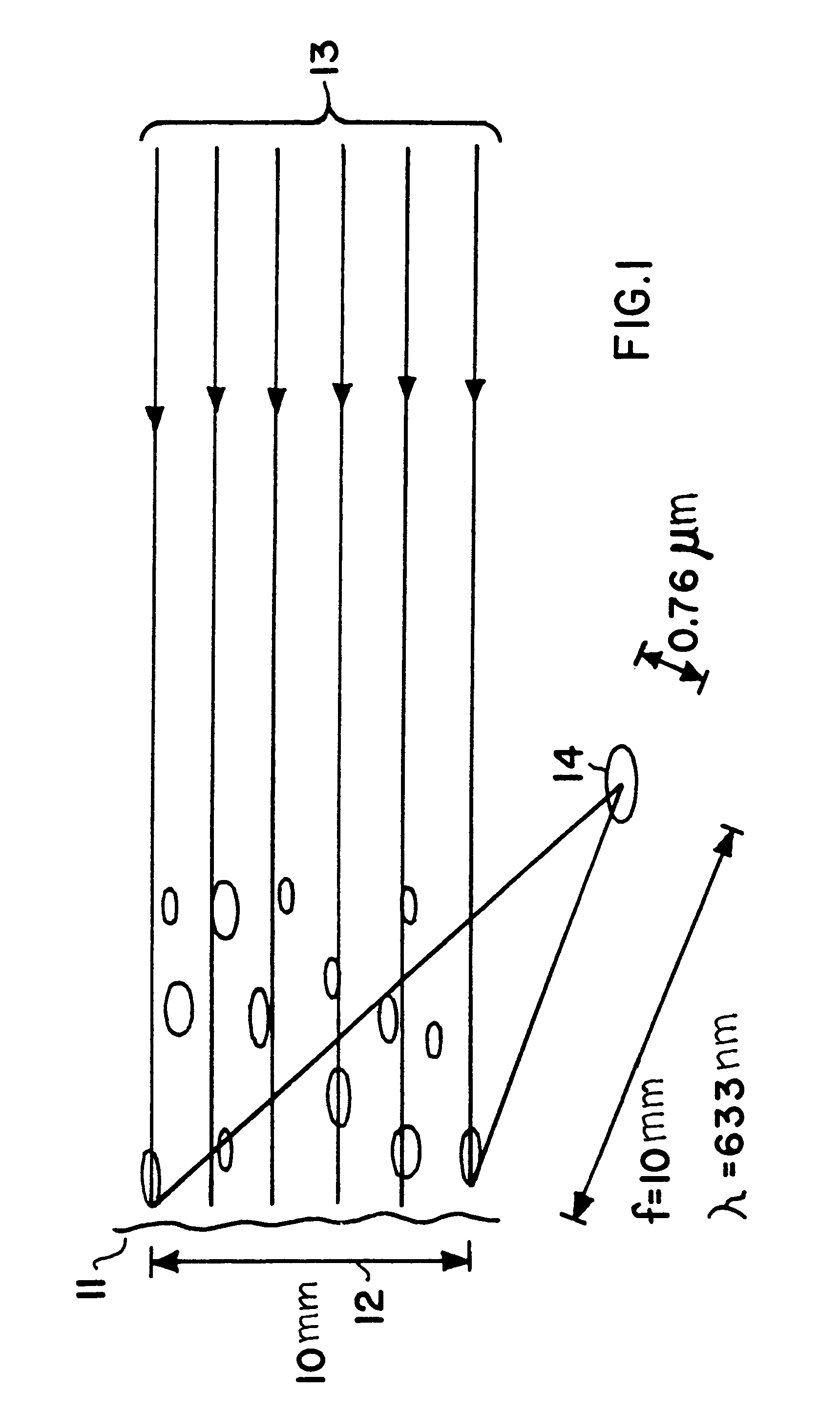
FIG. 1 shows the speckles in the near field of the projection screen 11. For a distance of 10 mm from the image spot 12 of an incoming projection beam 13 having a diameter of 10 mm, the speckles 14 have a diameter in the range of about 1 .mu.m for a wavelength .lambda.=633 nm. By way of a relative phase shift between the upper and lower edge of up to 2 .pi. it is possible to shift a speckle over its diameter and thereby average it away in the eye of the viewer with regard to space and time.

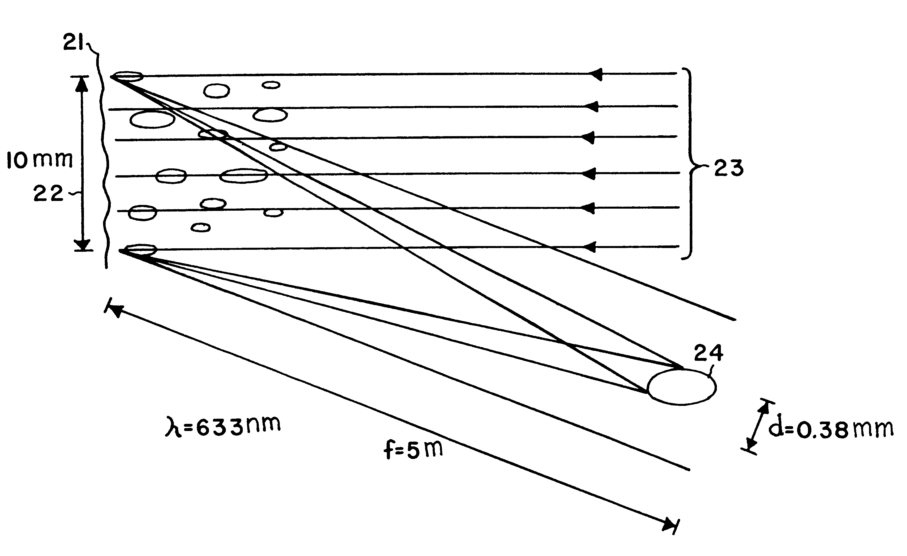
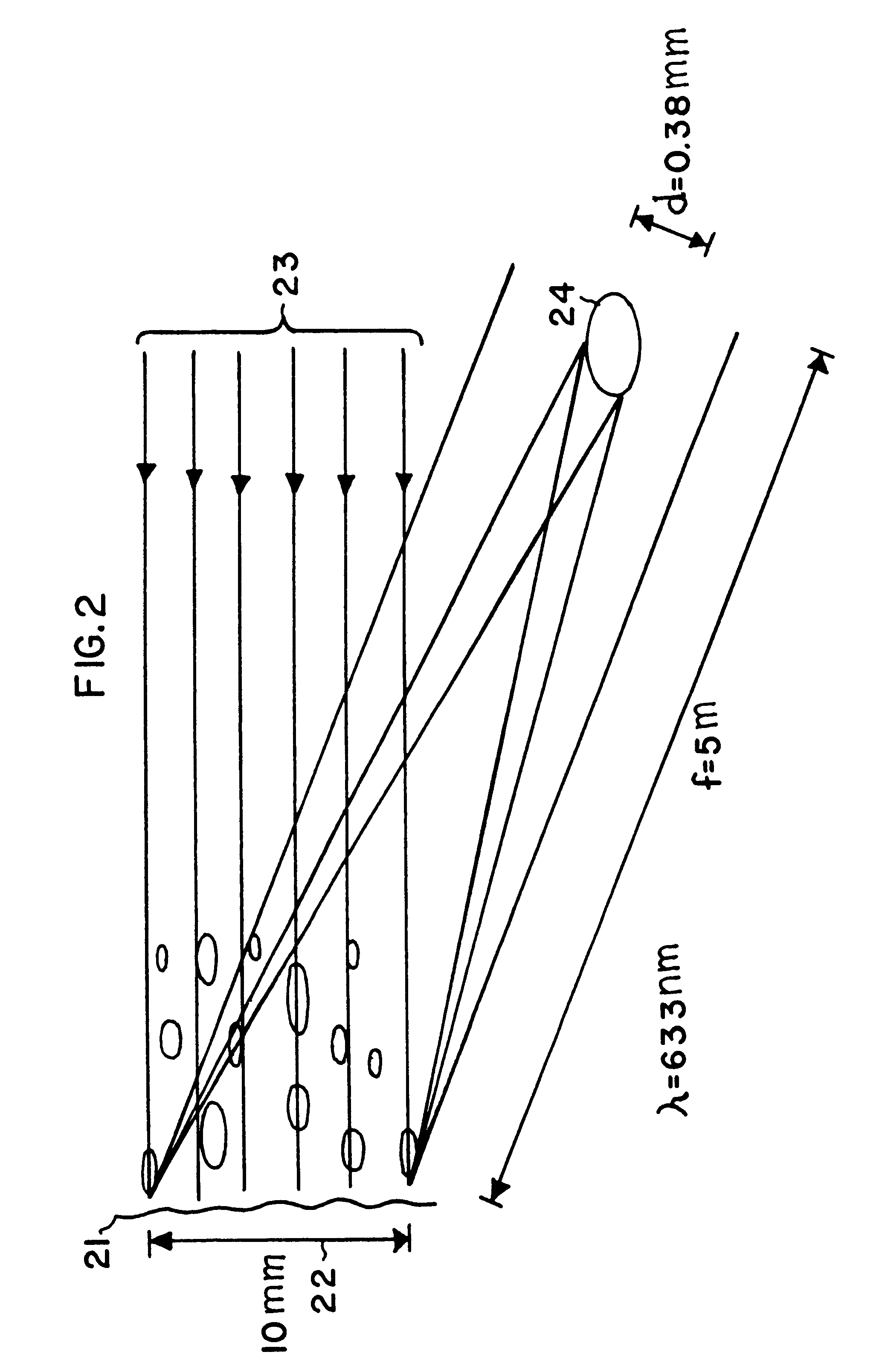
FIG. 2 shows speckles 24 in the distant field of the projection screen 21 corresponding to the situation of a large image laser projection 23 with a viewer spacing of 5 m and an image spot diameter 22 of 10 mm. The speckles 24 at the point of a viewer are already relatively large with a diameter of about 0.5 mm. A relative phase shift of the upper edge to the lower edge of the illumination beam provides only an unnoticeable displacement of the speckle at the viewer, whereby a reduction of the spec...


PUM


Abstract

A method for the elimination of image speckles in a scanning laser projection is suggested, in which a phase hologram is used for dividing the illumination beam of the projector into partial beams. The partial beams are heterodyned again on the image screen within the image element (pixels) to be projected in such a way that differing speckle patterns are formed which average each other out in the eye of the viewer over time and/or space. Thus, a device is provided especially for the laser projection which substantially eliminates or reduces the speckles at the viewer. However, the beam form and the beam density are hardly or not changed.

Description

The invention relates to a method for eliminating speckles in the distant field of a projection surface illuminated by a laser for example in connection with a laser image projection on an image screen and devices for its performance.BACKGROUND INFORMATIONWhen using lasers for the illumination or image display on a projection surface, interferences occur due to the roughness of the surface in the space in front of the projection surface due to transit time differences of the waves that emanate from different portions of the projection surface. These interferences lead to a strong additional intensity modulation of the brightness distribution of the image screen in the eye of the viewer. The intensity modulation covers the image as a fine granulation pattern forming an additional noise proportion in the image which reduces the discernible resolution by a factor of up to 10 and leads, in multi-color laser images, to a color falsification by an incomplete color summation, see in this c...

Claims


Application Information

Patent Timeline
Patent Type & Authority Patents(United States)
IPC IPC(8): G02B27/48G02B26/10H04N9/31
CPCG02B27/48G03H1/32G03H2240/11
Inventor WANG, LINGLITSCHUDI, THEOHALLDORSSON, THORSTEINNPETURSSON, PALMI
Owner EADS DEUT GMBH
Why Eureka
Try Eureka