Power factor correction control circuit and power supply including same

Inactive Publication Date: 2002-04-16
ARTESYN TECH
View PDF10 Cites 144 Cited by
  • Summary
  • Abstract
  • Description
  • Claims
  • Application Information

AI Technical Summary

Benefits of technology

The present invention provides an advantage in comparison with prior art power factor correction techniques because it is capable of more precisely limiting the input power. Using the PFC technique of the present invention, it is reasonable to expect the power limit accurac

Problems solved by technology

Average filtering and elimination of the capacitors is ordinarily not a practical solution considering size, weight, and performance specifications.
Such PFC control circuits, however, are limited in their ability to p

Method used


Image

  • Power factor correction control circuit and power supply including same
  • Power factor correction control circuit and power supply including same
  • Power factor correction control circuit and power supply including same

Examples


Embodiment Construction

It is to be understood that the figures and descriptions of the present invention have been simplified to illustrate elements that are relevant for a clear understanding of the present invention, while eliminating, for purposes of clarity, other elements of a boost power supply. For example, an inrush circuit for the boost converter is not shown herein. Those of ordinary skill in the art will recognize, however, that these and other elements may be desirable in a typical boost power supply with PFC. However, because such elements are well known in the art, and because they do not facilitate a better understanding of the present invention, a discussion of such elements is not provided herein.

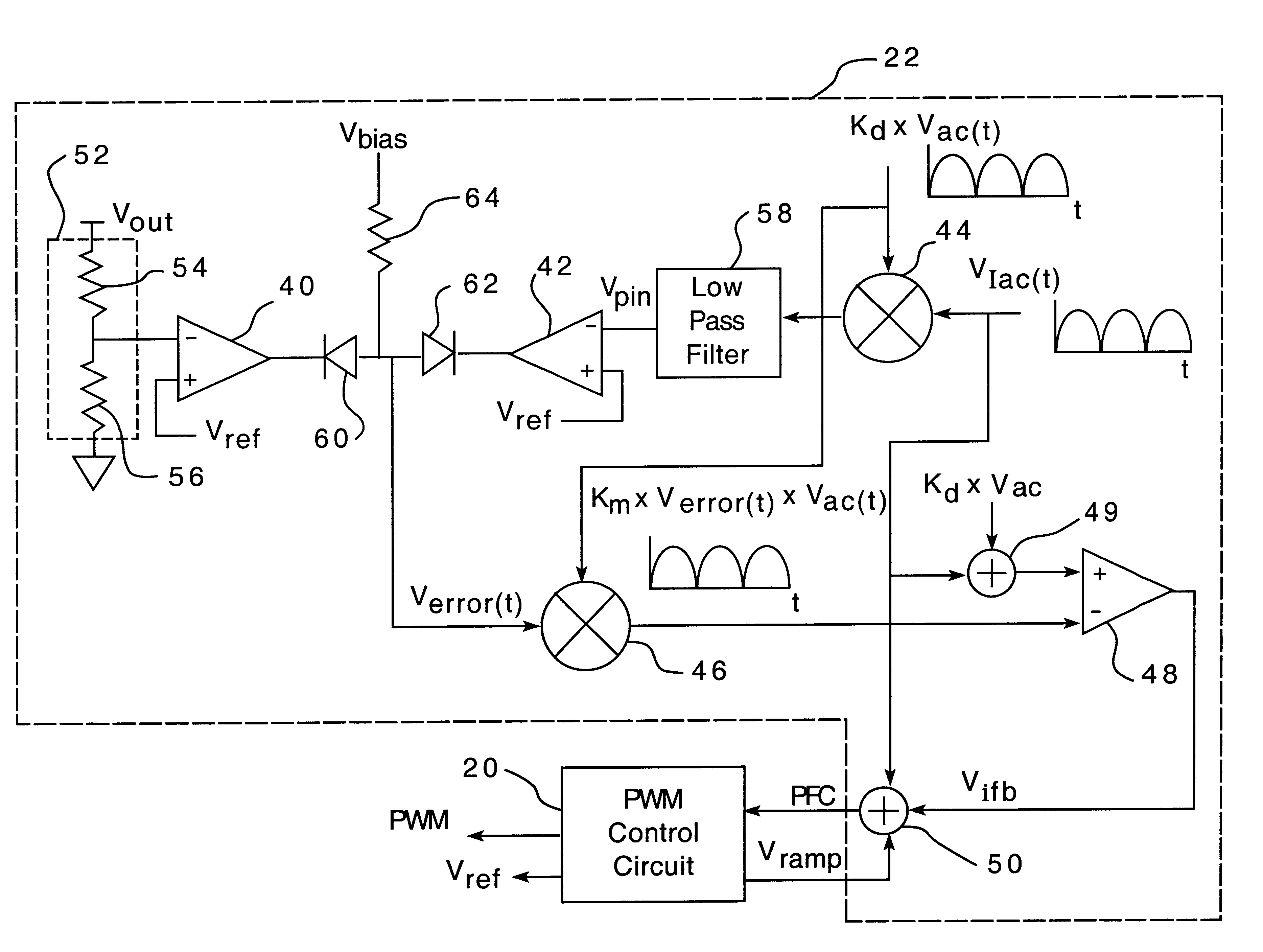
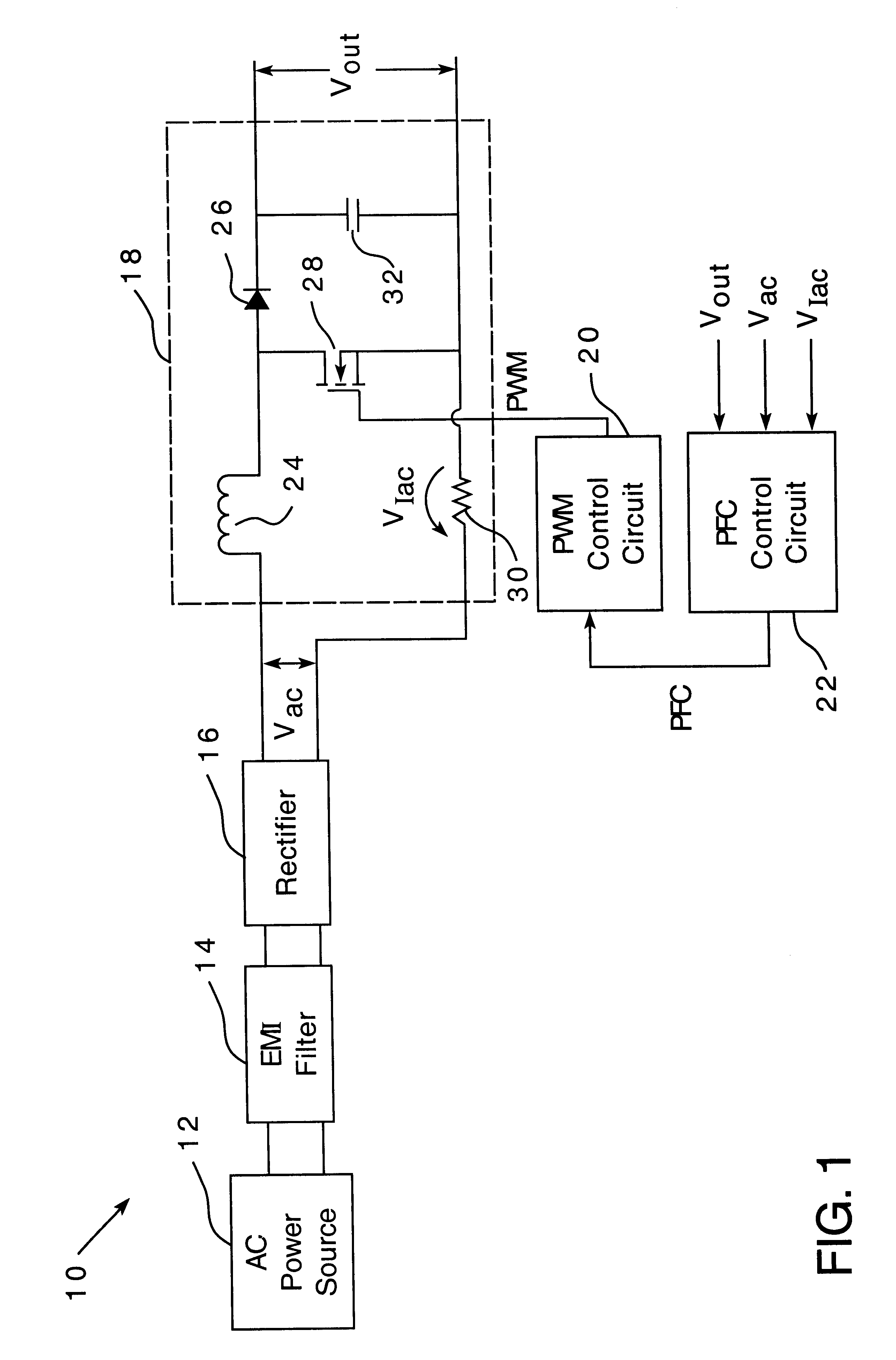
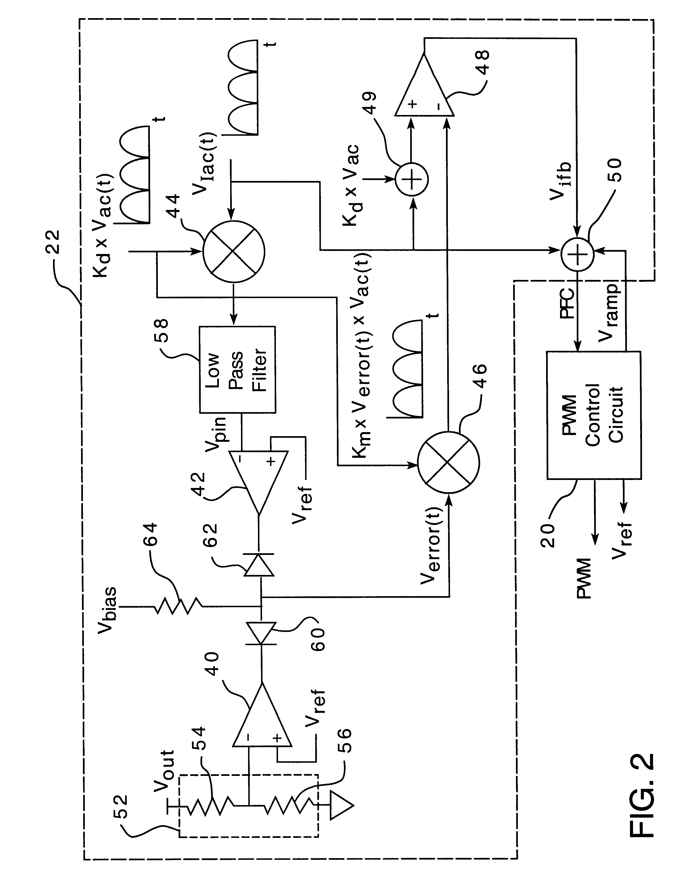
FIG. 1 is diagram of a boost power supply 10 according to one embodiment of the present invention. The power supply 10 includes an AC power source 12, an EMI filter 14, a rectifier circuit 16, a boost converter circuit 18, a pulse width modulator (PWM) control circuit 20, and a power factor corre...


PUM


Abstract

A power factor correction circuit for a boost power supply, wherein the boost power supply includes a boost converter responsive to a rectified AC line voltage. According to one embodiment, the power factor correction circuit includes a voltage feedback amplifier having a first input terminal responsive to an output voltage of the boost converter, a switching multiplier circuit having a first input terminal connected to an output terminal of the voltage feedback amplifier and a second input terminal responsive to the rectified AC line voltage, a current feedback amplifier having a first input terminal connected to an output terminal of the switching multiplier circuit and having a second input terminal responsive to an input current of the boost converter, and a pulse width modulator control circuit having an input terminal connected to an output terminal of the current feedback amplifier and having an output terminal for connection to a pulse width modulated switch of the boost converter.

Description

CROSS-REFERENCE TO RELATED APPLICATIONSNot Applicable.STATEMENT REGARDING FEDERALLY SPONSORED RESEARCH AND DEVELOPMENTNot Applicable.BACKGROUND OF INVENTION1. Field of InventionThe present invention relates generally to power electronics and, more particularly, to power factor correction (PFC) control circuits.2. Description of the BackgroundThe average power obtained from an AC line supply through an AC-to-DC power supply is always less than the product of the RMS (root mean square) voltage and the RMS current. The ratio of the average power to the product of the RMS voltage and the RMS current is known as the power factor. For example, a converter having a power factor of 70% means that the power drawn from the line supply is 70% of the product of the voltage and current in the line and, thus, only 70% of what could be obtained with a unity power factor.To increase the power factor of a power supply, and hence the efficiency of the power supply, it is known to employ power factor ...

Claims


Application Information

Patent Timeline
IPC IPC(8): H02M1/00H02M7/12H02M1/42H02M3/155
CPCH02M1/4225Y02B70/126Y02B70/10Y02P80/10
Inventor MARTINELLI, ROBERT M.
Owner ARTESYN TECH
Why Eureka
Try Eureka