Short circuit protection circuit for a pulse width modulation (PWM) unit

a protection circuit and pulse width technology, applied in the direction of power conversion systems, instruments, dc-dc conversion, etc., can solve problems such as degrading system reliability, and achieve the effects of reliable short circuit operation, reliable recovery from short circuit operation, and reduced system average input power

Active Publication Date: 2011-11-22
BCD SHANGHAI MICRO ELECTRONICS CO LTD
View PDF3 Cites 8 Cited by
  • Summary
  • Abstract
  • Description
  • Claims
  • Application Information

AI Technical Summary

Benefits of technology

[0019]It is a further object of the present invention to provide a reliable and effective method to identify the short circuit event in an emitter drive PWM system.
[0030]A method and circuit implementation to limit both instantaneous and average system input power during system output short circuit in emitter drive Pulse Width Modulated (PWM) switching mode power supplies are described. The opening of feedback loop is used to identify the output short circuit event in emitter drive PWM system. The lower limit of feedback voltage for normal PWM operation (UVLO lower triggering voltage) is used to limit the instantaneous system input power during short circuit operation. The PWM frequency is reduced during the system is in short circuit state so as to limit the system average input power. Normal PWM frequency is restored in one complete startup phase after a fixed time interval so that the system can be recovered from short circuit to normal operating state when the short circuit fault is removed. Thus, both the instantaneous and average system input power can be limited and system operates reliably under output short circuit conditions by applying this invention.

Problems solved by technology

It may cause PWM controller 200 or power transistor 124 or other device failure and degrade system reliability.

Method used


Image

  • Short circuit protection circuit for a pulse width modulation (PWM) unit
  • Short circuit protection circuit for a pulse width modulation (PWM) unit
  • Short circuit protection circuit for a pulse width modulation (PWM) unit

Examples


Embodiment Construction

[0039]The detailed descriptions for content and technology of the present invention associated with figures are as follows.

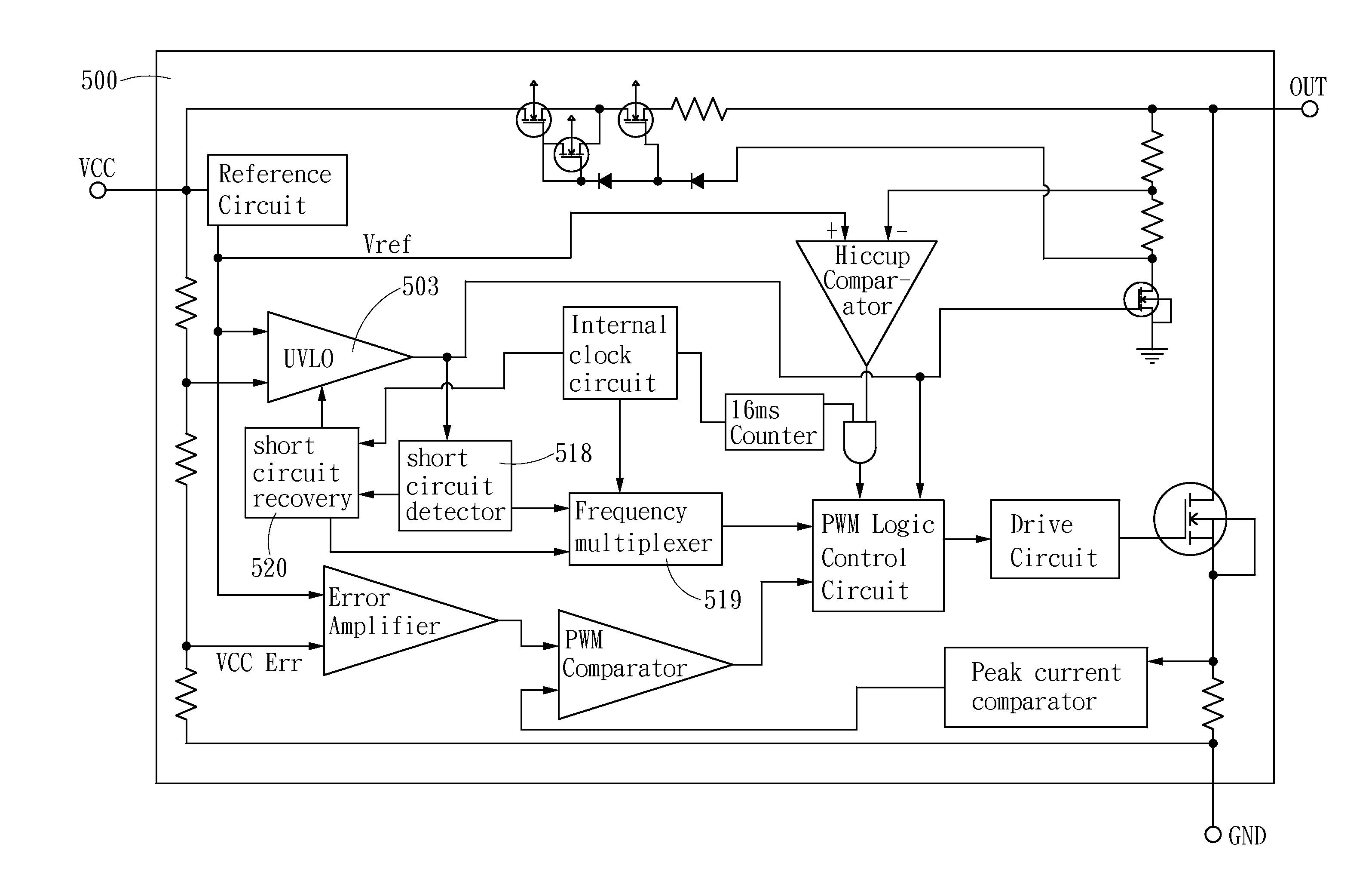
[0040]FIG. 5 is the functional block diagram of emitter drive PWM controller with short circuit protection of the present invention. The PWM controller 500 comprises a short circuit detector 518, Frequency multiplexer 519 and short circuit recovery circuit 520. When the short circuit event occurs, the frequency multiplexer 519 will change the switching frequency to short PWM frequency. After a pre-determined recovery time which is set in short circuit recovery circuit 520, the frequency multiplexer 519 will restore the switching frequency to normal PWM frequency.

[0041]FIG. 6 is one implementation of system recovery after short circuit condition is removed.

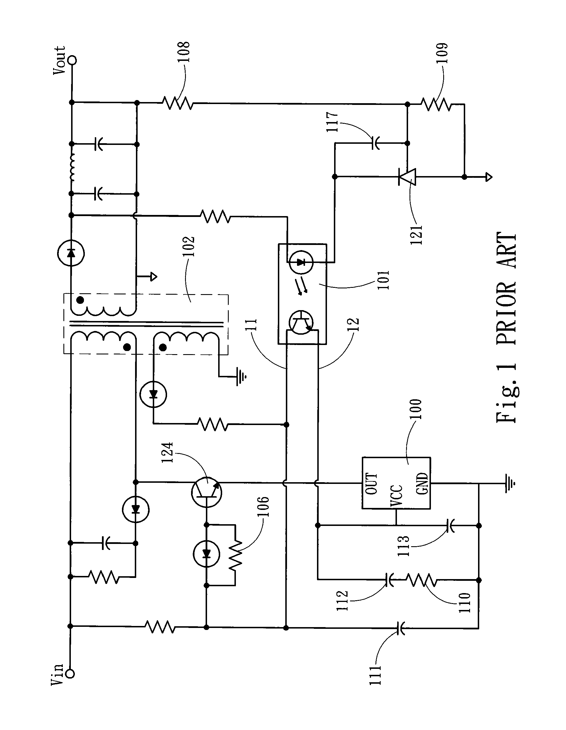
[0042]When Vout is shorted, the VCC capacitors 112, 113 (as seen in FIG. 1) will be charged and discharged periodically due to the repeated startup and UVLO process of open loop operation. The OUT pin switching...


PUM


Abstract

A short circuit protection circuit for a pulse width modulation (PWM) unit which includes a PWM logic control circuit, an under voltage lookout (UVLO) circuit and an internal clock circuit; wherein the UVLO circuit detecting a bias power (Vcc) and delivering an UVLO signal when the bias power is judged excessively low, the PWM unit further comprising: a short circuit detector, a short circuit recovery circuit and a frequency multiplexer. The short circuit detector is to detect the UVLO signal and generate a short signal. The short circuit recovery circuit to set a pre-determined recovery time and generate a recovery signal when the pre-determined recovery time ends. The frequency multiplexer which is triggered by the short signal when the short circuit event occurs to change a switching frequency to a short PWM frequency, and triggered by the recovery signal to restore the switching frequency.

Description

FIELD OF THE INVENTION[0001]A short circuit protection circuit for a pulse width modulation (PWM) unit is to limit system input power during output short circuit operations of emitter drive switching mode power supplies.BACKGROUND OF THE INVENTION[0002]Compared with linear regulators, switching mode power supplies have the advantages of smaller size higher efficiency and larger output power capability.[0003]Pulse Width Modulation (PWM) is one of major control architectures applied in switching mode power supplies. Emitter drive PWM control has the advantage of fewer pin counts compared with base drive PWM control.[0004]FIG. 1 is an emitter drive switching mode power supply system which includes an emitter drive PWM controller coupled with a primary winding of the transformer through a high voltage NPN power transistor. Energy is transferred to secondary winding from the primary winding in a manner controlled by the PWM controller to provide a constant DC output voltage. The auxiliar...

Claims


Application Information

Patent Timeline
Patent Type & Authority Patents(United States)
IPC IPC(8): H02M3/335
CPCH02M3/33507H02M1/32
Inventor FANG, SHAO-HUACHEN, CHAODUAN, JIAN-HUAZHU, YA-JIANG
Owner BCD SHANGHAI MICRO ELECTRONICS CO LTD
Why Eureka
Try Eureka