Color transmission system discrimination circuit in television set

a color transmission system and discrimination circuit technology, applied in the field of color transmission system discrimination circuit in television sets, can solve the problems of affecting the correct setting of the color transmission system, and affecting the appearance of the screen, so as to prevent the disturbance of the screen and the appearance

Inactive Publication Date: 2002-04-23
PANASONIC CORP
View PDF4 Cites 4 Cited by
  • Summary
  • Abstract
  • Description
  • Claims
  • Application Information

AI Technical Summary

Benefits of technology

In the case where a discrimination signal output from the discrimination decoder represents monochrome broadcasting, it is preferable that the sequencer returns to the first stage without performing the fourth stage. According to this structure, when monochrome broadcasting is switched to color broadcasting, a discrimination result already has been output from the discrimination decoder. Therefore, a color transmission system is determined in a short period of time, and a predetermined switching of settings is conducted.
Furthermore, it is preferable that the above-mentioned color transmission system discrimination circuit includes means for, in the first to third stages, fixing a trap frequency of a trap filter circuit for removing a color signal component from a video composite signal so as to prevent disturbance of the screen and the appearance of color noise, fixing a color demodulation circuit to a PAL / NTSC circuit or a SECAM circuit, and setting a color level of the color demodulation circuit and a color amplifier at a minimum value.
Furthermore, in each of the above-mentioned structures, it is preferable that a color transmission system is provisionally set in the second stage so as to have higher priority (e.g., possibility), compared with the first stage, and a color transmission system is provisionally set in the third stage so as to have higher priority, compared with the second stage. Because of this, in the case where a color transmission system is switched at random timing, as the priority of the switched color transmission system is higher, the period of time required for discrimination and decision becomes shorter in terms of probability.

Problems solved by technology

However, the above-mentioned conventional discrimination circuit has several problems.
Therefore, it takes a long period of time for a color transmission system to be correctly set.
This lengthens the period of time for a color transmission system to be correctly set, and leads to a detection error in the SECAM system.
That is, the third problem is difficulty in detecting more color transmission systems.
However, according to this method, the SECAM system of 60 Hz cannot be determined.
Actually, no countries have adopted this system as far as a ground wave is concerned.

Method used


Image

  • Color transmission system discrimination circuit in television set
  • Color transmission system discrimination circuit in television set
  • Color transmission system discrimination circuit in television set

Examples


embodiment 1

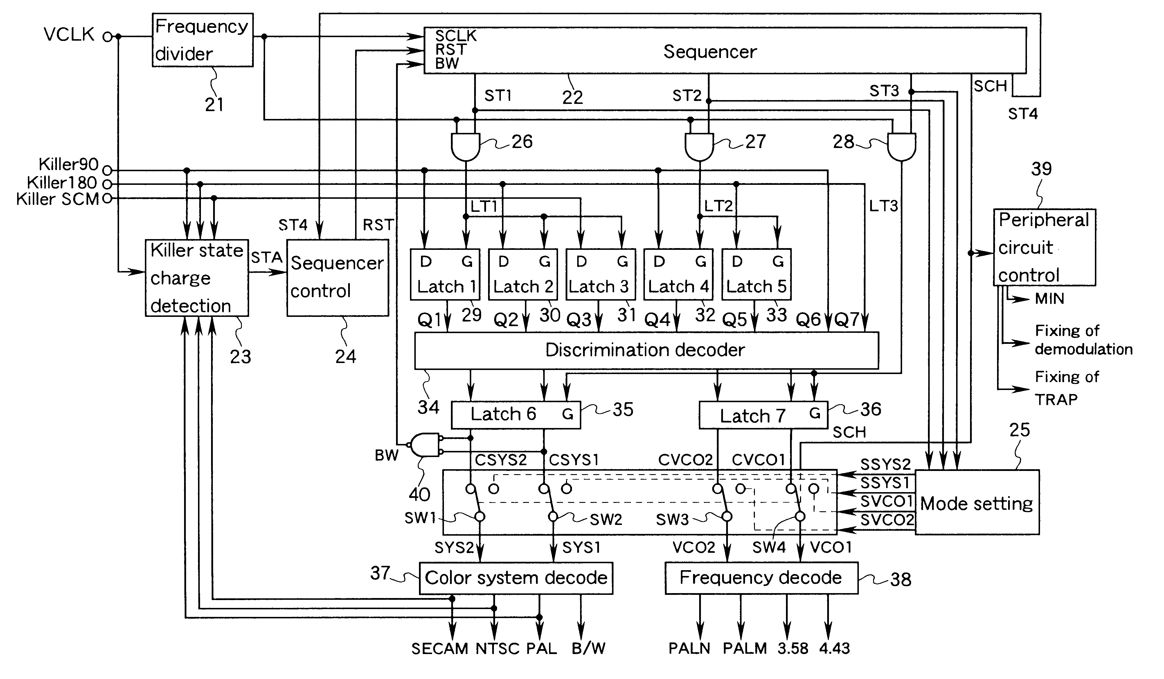
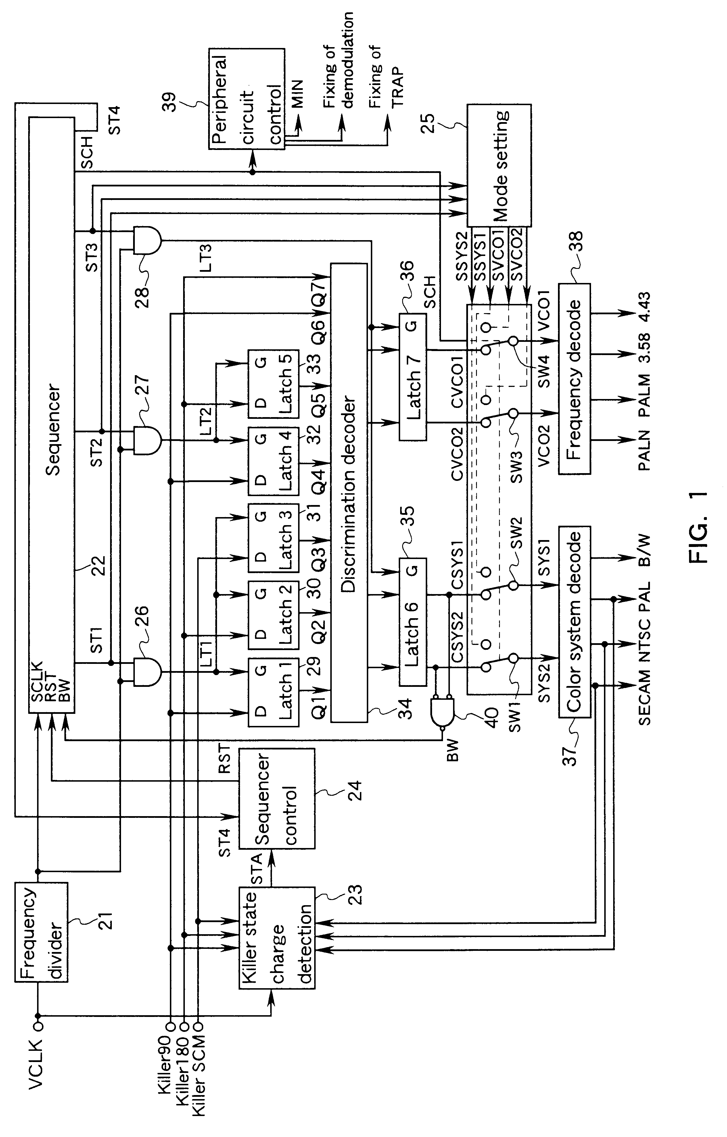
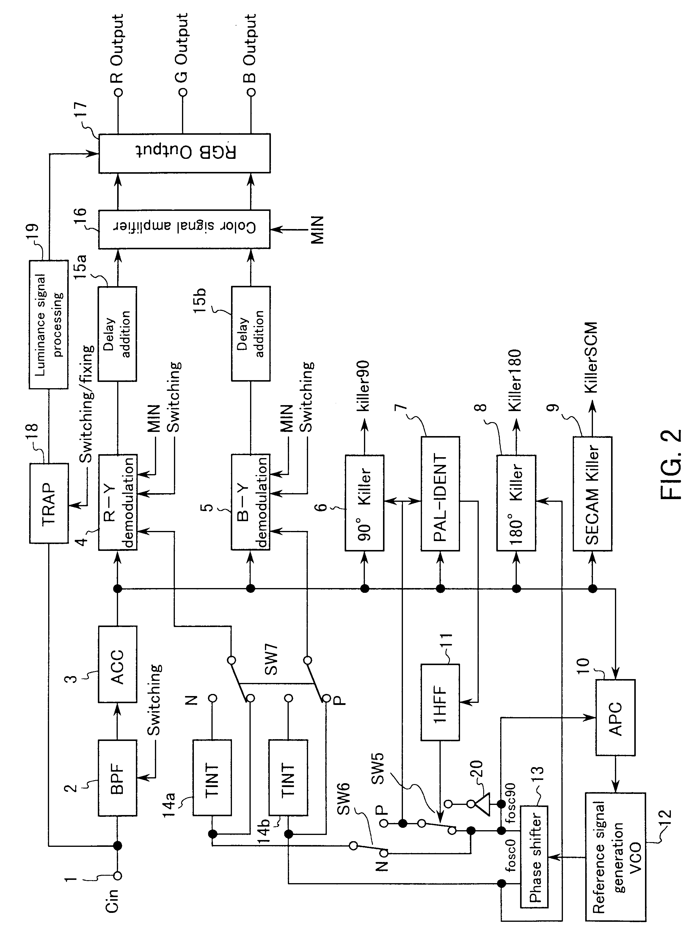
FIG. 1 is a block diagram showing a color transmission system discrimination circuit in Embodiment 1 of the present invention. FIG. 2 is a block diagram showing a peripheral circuit of the color transmission system discrimination circuit, i.e., a circuit for switching various settings in accordance with a color transmission system. First, the circuit shown in FIG. 2 will be described.

Referring to FIG. 2, a video composite signal C.sub.in input through an input terminal 1 is input, through a band-pass filter (BPF) 2 and an automatic color control circuit (ACC) 3, to an R-Y demodulation circuit 4, a B-Y demodulation circuit 5, a 90.degree. killer signal detection circuit 6, a PAL-IDENT circuit 7, a 180.degree. killer signal detection circuit 8, a SECAM killer signal detection circuit 9, and an APC circuit 10 forming a reference signal generation circuit. The BPF 2 is switched in accordance with a color transmission system; that is, one is selected from the following three: a BFP for 4...

embodiment 2

In a color transmission system discrimination circuit in Embodiment 2 of the present invention, discrimination is performed by using a software program. Provisional color transmission systems are successively set in three stages, and a color transmission system is determined based on three killer signals thus obtained. This is the same as that in Embodiment 1. The present embodiment will be described with reference to flow charts in FIGS. 7 and 8.

At Step S1 in FIG. 7, it is checked whether or not a killer signal is changed. This corresponds to the function of the killer state change detection circuit 23 in Embodiment 1 shown in FIG. 1. Next, at Step S2, it is detected whether or not a color transmission system is for the European countries. If it is for the European countries, Step S3 and the subsequent steps are conducted. If it is not for the European countries, i.e., if it is for South America, Step S12 and the subsequent steps in FIG. 8 are conducted. Whether or not it is for th...


PUM


Abstract

In a receiver capable of receiving a plurality of television systems, a color transmission system discrimination circuit is provided, which is capable of exactly and rapidly determining a color transmission system which is being received. The color transmission system discrimination circuit includes: a killer state change detection circuit 23 for detecting a change in three kinds of color killer signals corresponding to a burst signal component in a 90° phase, a burst signal component in a 180° phase, and a SECAM discrimination signal; a sequencer 22 which is driven with an output signal of the killer state change detection circuit 23 and performs the first, second, and third stages in this order respectively for a predetermined period of time; first latch circuits 29 to 31 for latching the color killer signal captured in the first stage; second latch circuits 32 and 33 for latching the color killer signal captured in the second stage; and a discrimination decoder 34 for outputting a discrimination signal of a color system and a discrimination signal of a frequency of a reference sub-carrier signal, based on the color killer signal captured in the third stage and the output signals of the first and second latch circuits 29 to 33.

Description

The present invention relates to a color transmission system discrimination circuit in a television receiver designed for a plurality of television systems.In general, a color system or a color transmission system refers to three systems such as PAL, SECAM, and NTSC. Actually, including variations of frequencies of a reference sub-carrier signal, about 10 kinds of color transmission systems have been used in the world. A reference sub-carrier signal has 4 kinds of frequencies: 3.58 MHz in the NTSC system, 4.43 MHz in the PAL system, a frequency slightly lower than 3.58 MHz in the PAL-M system, and a frequency slightly higher than 3.58 MHz in the PAL-N system.Recently, television receivers designed for a multi color-transmission system have been developed and put into practical use, which are capable of carrying out processing in accordance with the above-mentioned plurality of kinds of color transmission systems. Such a receiver typically is equipped with a color transmission system...

Claims


Application Information

Patent Timeline
Patent Type & Authority Patents(United States)
IPC IPC(8): H04N9/64H04N9/70H04N5/46
CPCH04N5/46H04N9/70H04N9/642H04N9/00
Inventor OKAMOTO, NAOKIMISAKU, TAKESHI
Owner PANASONIC CORP
Why Eureka
Try Eureka