Communications system

Inactive Publication Date: 2002-04-23
BRITISH TELECOMM PLC
View PDF6 Cites 133 Cited by
  • Summary
  • Abstract
  • Description
  • Claims
  • Application Information

AI Technical Summary

Problems solved by technology

Such an arrangement provides only a limited degree of protection against attacks intended to defeat a security system.
The signals transmitted

Method used


Image

  • Communications system
  • Communications system
  • Communications system

Examples


Embodiment Construction

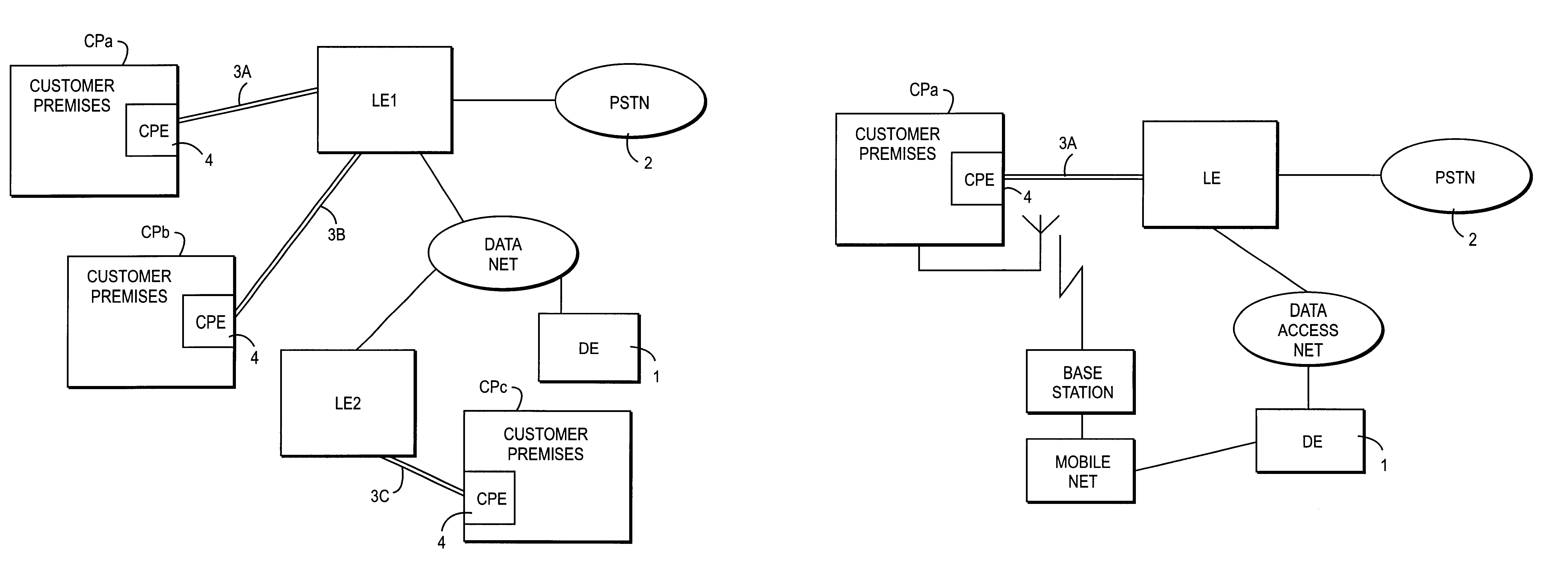
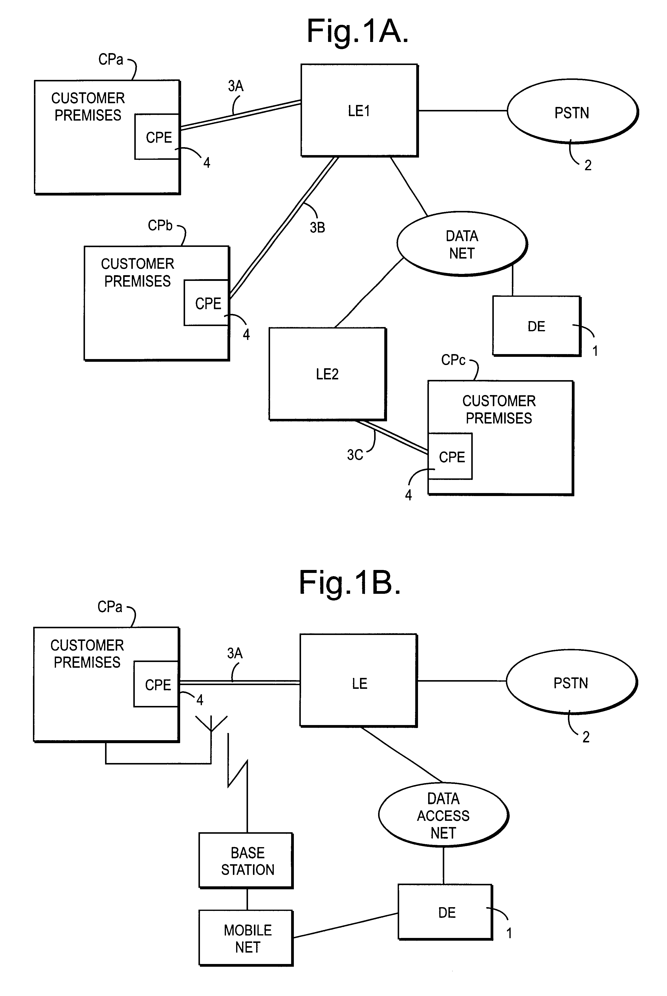
A communications system includes a control station 1 which incorporates a data engine DE. Data is received at the data engine via local exchanges LE1, LE2 of a telecommunications network 2. The local exchanges are linked by ISDN lines 3a, 3b, 3c to remote terminals, 4, at different customer premises CPa, CPb, CPc. A number of different local exchanges are linked via a data access network to the control station 1. Although for the purposes of illustration only three customer premises are shown, in practice, many more terminals may be linked to a particular control station. The present example can accommodate 1024 individually addressable units at each of the customer premises. In this example the remote terminals 4 are the control panels of security alarm systems arranged to communicate with an alarm monitoring centre via the control station 1. The terminals 4 are also referred to herein as "customer premises equipment" (CPE).

The ISDN connections between the customer premises and the...


PUM


Abstract

A communications system includes a telecommunications link (3) between a remote terminal (CPa-c) (such as a burglar alarm control panel) and a control station (1). Polling requests are transmitted on a digital messaging channel which is carried by the telecommunications link. The remote terminal (CPa-c) generates a poll response message which is partially encrypted and is returned on the digital messaging channel to the control station where it is decoded.

Description

1. Field of the InventionThe present invention relates to a system for monitoring remote terminal equipment, such as a security alarm, over a telecommunications link.2. Related ArtThere are a number of situations in which it is necessary to monitor at a central site the status of terminals at remote locations. One example is provided by burglar alarm systems of the type which send an alert to a monitoring service. Conventionally, a telephone line has been used to provide the connection between the alarm equipment at the customer premises and the monitoring station. An analogue tone is transmitted on the line to the local exchange and is used for signalling between the alarm and the monitoring station, including the transmission of alarm signals. Such an arrangement provides only a limited degree of protection against attacks intended to defeat a security system. If the tone is interrupted by the line being cut, then this is detected at the monitoring station. The signals transmitted...

Claims


Application Information

Patent Timeline
IPC IPC(8): G08B26/00H04M11/04H04Q11/04G08B25/00G08B25/01H04L12/28H04L12/56H04Q9/00
CPCG08B26/00H04Q11/0435H04M11/04H04W74/06H04Q2213/1301H04Q2213/13036H04Q2213/13092H04Q2213/13098H04Q2213/13176H04Q2213/13196H04Q2213/13204H04Q2213/13209H04Q2213/13216H04Q2213/13296H04Q2213/1337H04Q2213/13389H04W8/26H04W12/02H04W12/037
Inventor KNIGHT, RICHARD RPARKINSON, DAVID WTUCK, ROBERT E
Owner BRITISH TELECOMM PLC
Why Eureka
Try Eureka