Patient table in combination with biomedical apparati like magnetic resonance imaging machine

a technology of magnetic resonance imaging machine and patient table, which is applied in the field of patient table, can solve the problems of high purchase and installation cost, inability to place in premises, and large machines are generally cumbersome and heavy

Inactive Publication Date: 2002-04-23
ESAOTE
View PDF11 Cites 23 Cited by
  • Summary
  • Abstract
  • Description
  • Claims
  • Application Information

AI Technical Summary

Benefits of technology

One embodiment provides that said recesses have a much smaller size than the overall supporting surface of the table and that they form open spaces in said supporting plane, such that they can be covered by the patient body without affecting the support thereof.
The mutual penetration of the work or operating surface and the table allows a considerable reduction of the overall size. Modular solutions of removable complementary inserts allow a table to fit several different operating or work surfaces. The latter are not only work surfaces or operating zones of the machines, but may be also surfaces equipped for performing manual interventions. Hence, one table can fit several different operating conditions, so that the patient need not be frequently transferred for the different interventions.
Particularly, the table provides considerable advantages, when used in combination with Nuclear Magnetic Resonance Imaging machines. In such machines, this configuration equals that of a machine having a C-shaped magnet, i.e. whose cavity may be accessed from three sides of its perimeter. Here, the lower horizontal side of the cavity is the side or surface which is to complement the U-shaped recess of the table.

Problems solved by technology

This solution involves a huge size of machines, which have a very high purchase and installation cost.
Large machines are generally cumbersome and heavy and cannot be placed in premises having a normal construction as regards volume and resistance of floors.
This involves cost increases, which are added to the higher cost of the machine.
In Nuclear Magnetic Resonance Imaging machines, the weight problem is important, and the dimensional problem also affects installation costs when, for instance, machines must be enclosed by shielding cages which, by their huge volume, usually have no light construction.
Further problems also arise when the patient is to be disposed in different orientations within a predetermined range.
Here, conventional tables, particularly when combined with low or medium cost machines, involve a considerably larger potential overall size of the table-machine combination.

Method used


Image

  • Patient table in combination with biomedical apparati like magnetic resonance imaging machine
  • Patient table in combination with biomedical apparati like magnetic resonance imaging machine
  • Patient table in combination with biomedical apparati like magnetic resonance imaging machine

Examples


Embodiment Construction

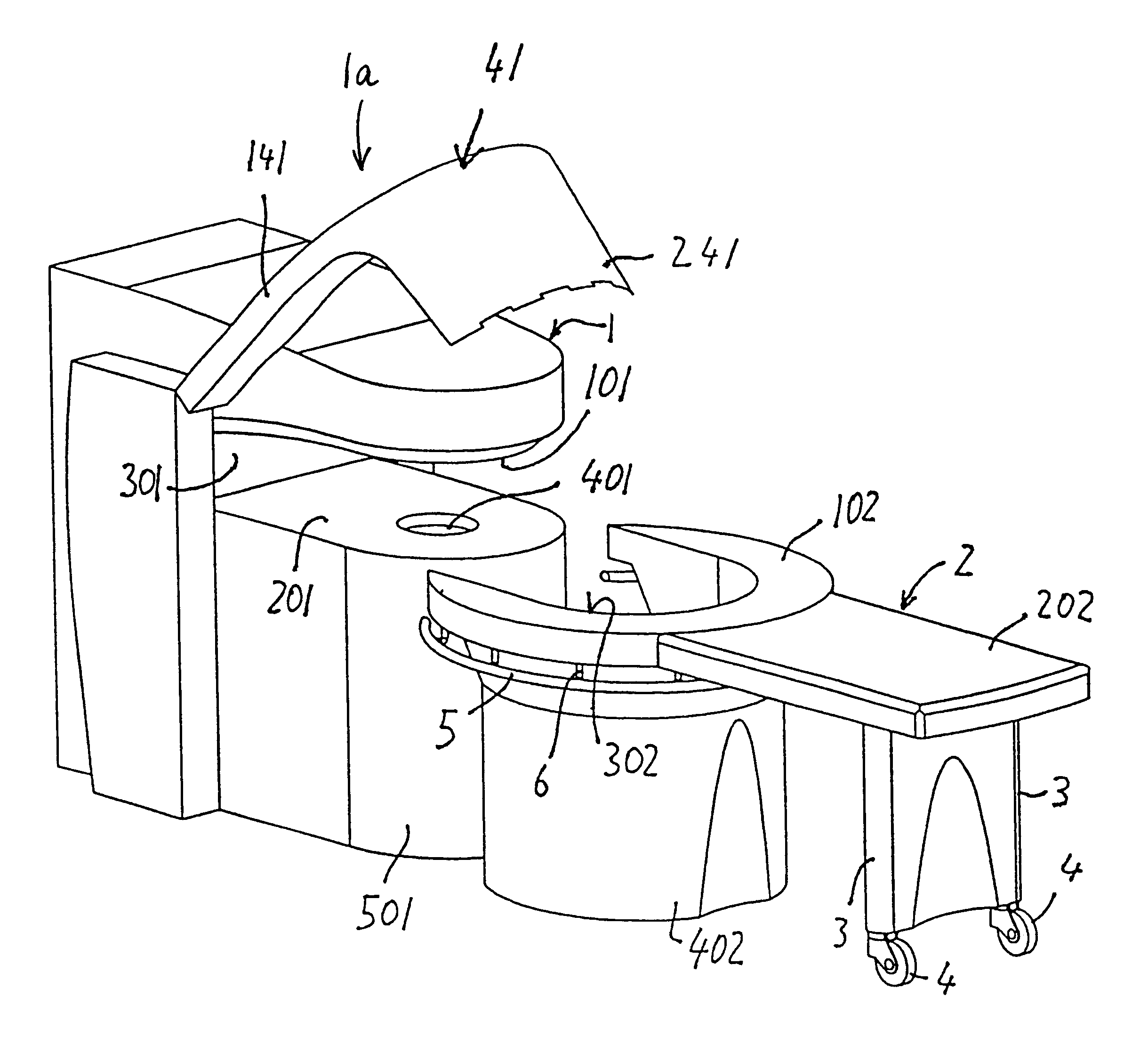
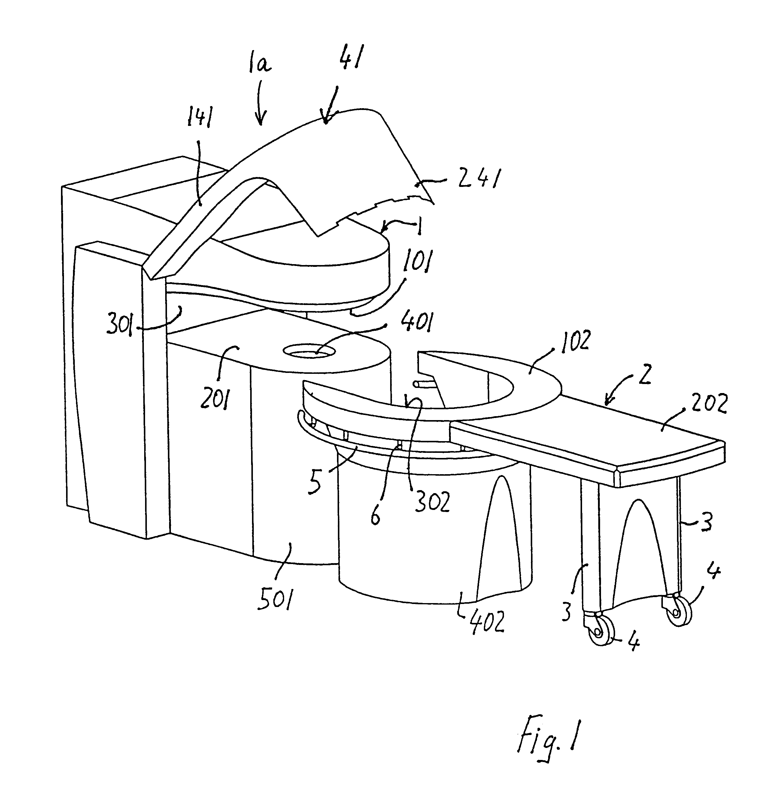
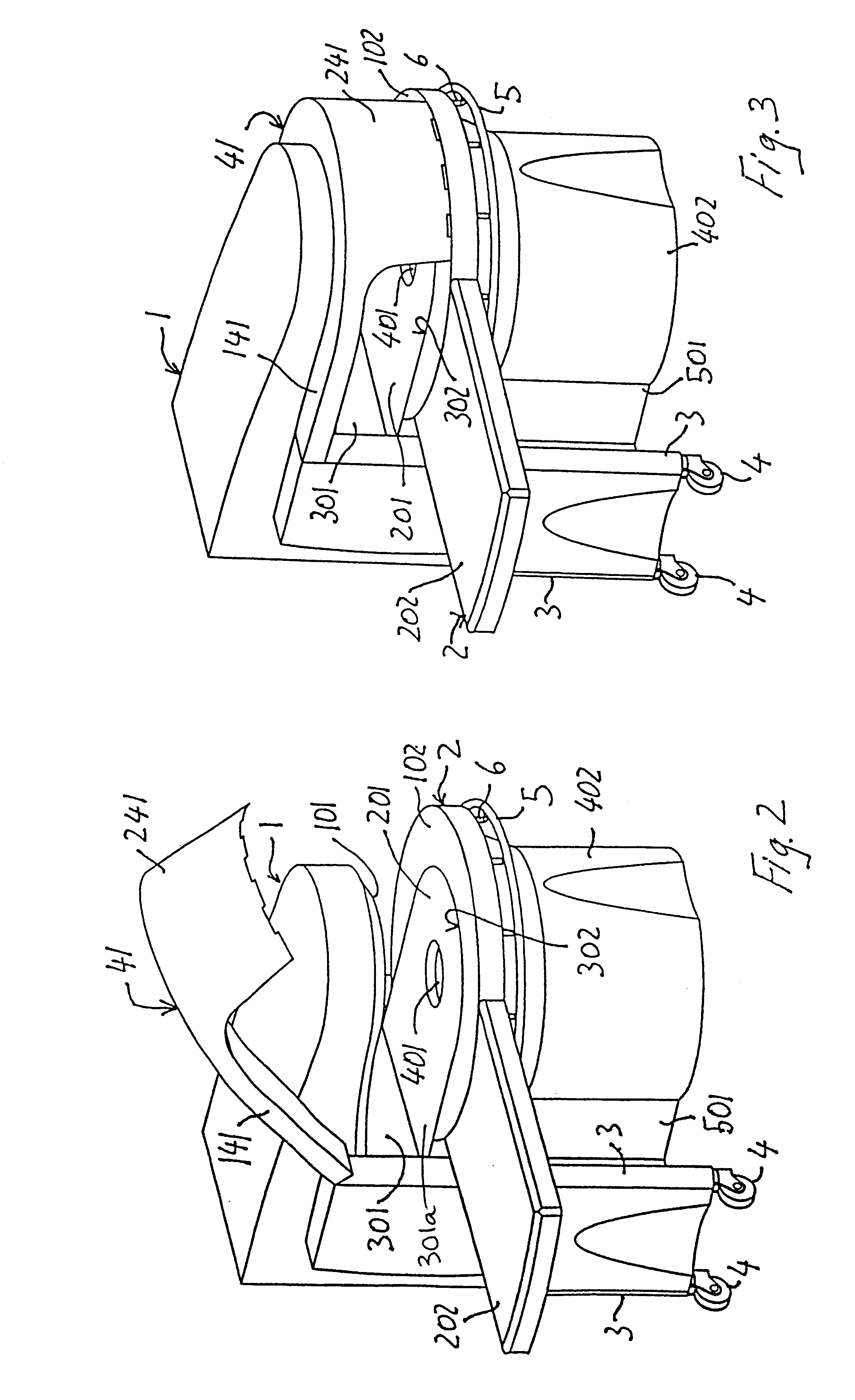
The embodiments illustrated herein particularly relate to a combination of a table according to the invention and a Nuclear Magnetic Resonance Imaging machine. This combination shall not be deemed to be limited to the scope of the invention. In fact, instead of the lower horizontal side 201 of the magnet cavity, which side 201 complements the recess 301a of the table, the part for complementing the recess 302 of the table may consist of work or operating surfaces, or sides for delimiting operating chambers of any type and / or of any machine for diagnosis and / or therapy.

Since in Nuclear Magnetic Resonance machines, the problems to reduce costs and dimensions are very important, and still directly connected to each other, the combination illustrated and described herein consists of a table and of a Nuclear Magnetic Resonance Imaging machine, and particularly includes a low or medium cost and a low or medium sized machine.

Referring to FIGS. 1 to 9, a Nuclear Magnetic Resonance Imaging m...


PUM


Abstract

A patient table is used in combination with a biomedical apparatus such as a magnetic resonance imaging machine. The table includes a supporting surface sized to accommodate at least a part of the patient's body. At least one recess is formed in one or more areas of the supporting surface, these recesses being open at the peripheral edge of the supporting surface. The table is formed of first and second parts that can be angled relative to one another. The table can be swung horizontally to relative positions relative to the machine and locked in selected ones of the positions.

Description

1. Field of the InventionThe invention relates to a patient table, or similar, particularly in combination with biomedical apparati like magnetic resonance imaging machine comprising a supporting surface which has such a size as to be able to accommodate at least a part of the patient body.2. Description of Related ArtAt present, patient tables, especially those for bearing the patient during diagnostic and therapeutic treatment, by using machines for diagnosis and therapy, are deemed to be separate from the structure of these machines. In order to allow limbs or anatomic regions of the patient body to be inserted into the operating area of the machine, such as an operating surface, a chamber or a cavity two solutions are essentially applied.When machines allow to do so, the table, having a substantially conventional shape is fully or partially inserted into the structure thereof. This solution involves a huge size of machines, which have a very high purchase and installation cost. ...

Claims


Application Information

Patent Timeline
Patent Type & Authority Patents(United States)
IPC IPC(8): A61B5/055A61B6/04
CPCA61B5/0555A61G13/1285A61B6/04A61B5/055A61B5/704
Inventor CARROZZI, ALESSANDROREZZONICO, FABIOCONTRADA, ORFEOSARASSO, GIANNIFACHINATO, ALESSIO
Owner ESAOTE
Why Eureka
Try Eureka