Baler with a weighing device

Inactive Publication Date: 2002-04-30
AGCO WOLFENBUETTEL GMBH
4 Cites 68 Cited by

AI-Extracted Technical Summary

Problems solved by technology

This limits the driving speed and causes high oscillation loads.
A further drawback of such an arrangement consists in that it is one-sided, which results in imprecise weighing results.
In addition, no device is provided which would correct false weighing results caused by transverse or longitudinal tilt of the b...

Abstract

An agricultural baler including a compression chamber housing, a support axle, springs provided at both sides of the compression chamber housing for supporting the housing on the support axle with a possibility of vertical displacement relative to the support axle, and sensors for determining a distance between the compression chamber housing and the support axle and for generating signals representing in response to sensing the distance a measure of a bale weight.

Application Domain

SuspensionsBaling +5

Technology Topic

EngineeringVertical displacement

Image

  • Baler with a weighing device
  • Baler with a weighing device

Examples

  • Experimental program(1)

Example

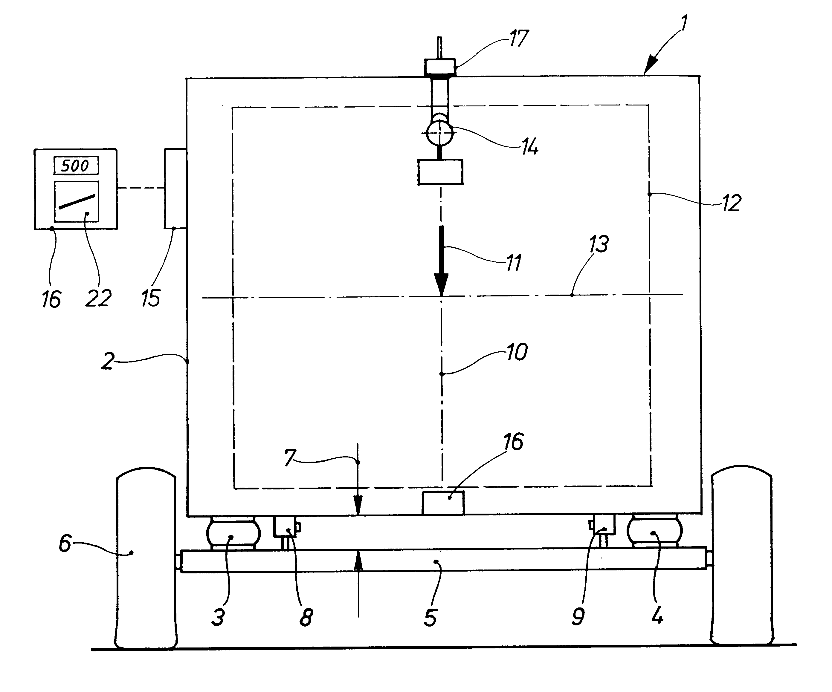
FIG. 1 shows a round baler 1 that essentially consists of a compression chamber housing 2 with a variable or constant compression chamber for producing cylindrical compressed bales, and of a drawbar, not shown, for connecting the baler to a tractor, likewise not shown.
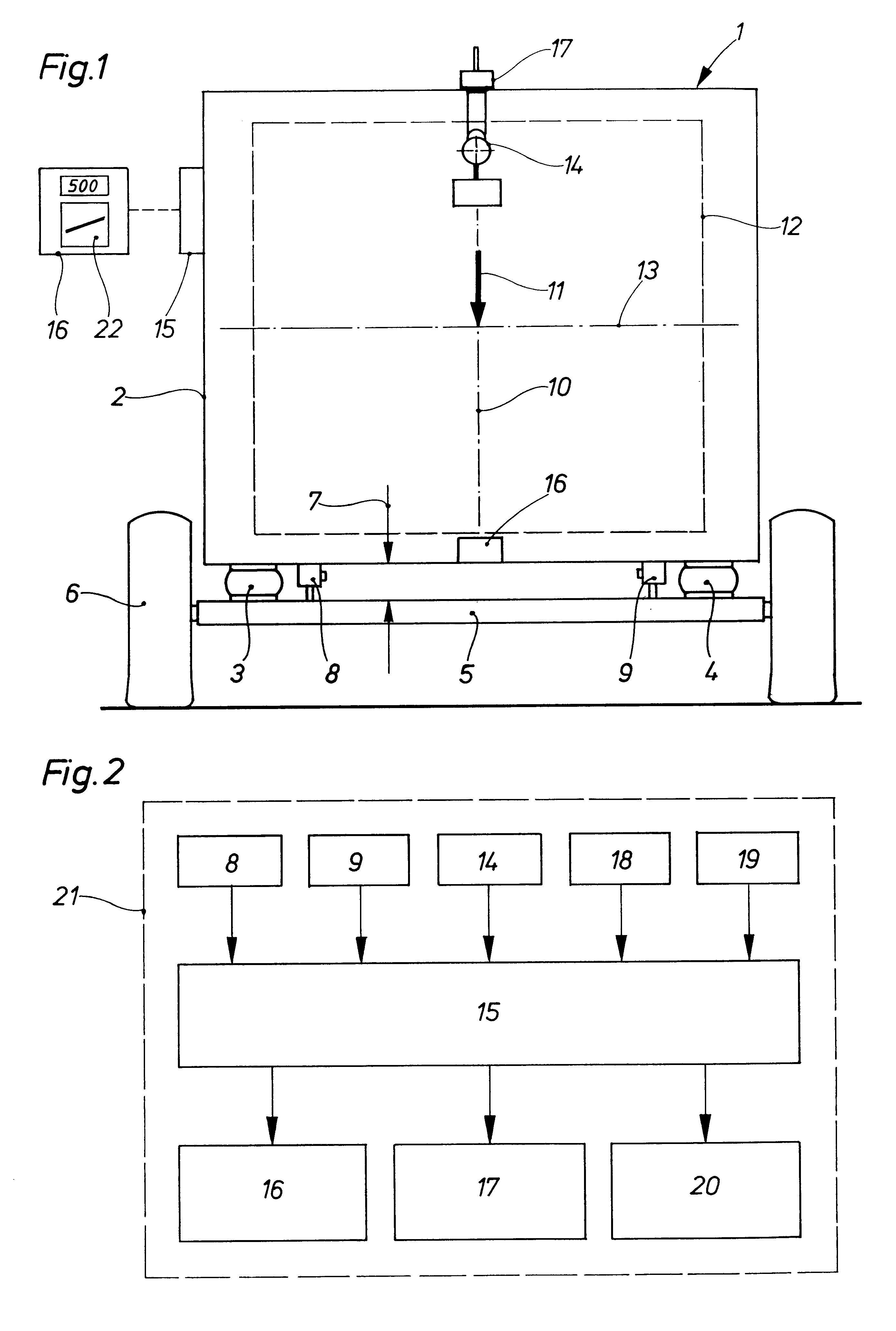
The compression chamber housing 2 is supported with two rubber springs 3 and 4 on a support axles 5 provided at its opposite ends with wheels 6. Upon filling of the round baler 1, the distance 7 between the compression chamber housing 2 and the support axle 5 is reduced dependent on the weight of the harvest filling the baler 1. The distance corresponding to the spring deflection is sensed by displacement sensors 8 and 9 the signals of which are used for displaying the bale weight. The sensors 8 and 9 are arranged symmetrically with respect to a vertical longitudinal central plane 10 and adjacent to respective rubber springs 3 and 4.
By evaluating the change in distances at separate sensors 8 and 9, the non-uniformity of the bale shape can be shown in a particularly simple manner. This non-uniformity may be caused by one-sided filling of the round baler 1.
In a horizontal position of the round baler 1, a vertically downward directed weight 11 of a round bale 12, which has a cylinder center axis 13 and which is shown in FIG. 1 with dash lines, is applied at the baler gravity center. In order to correct the false weight measurement of a bale, which may be caused by a longitudinal and/or transverse tilt of the baler, there is provided a gimbal-mounted pendulum 14. The round baler 1 can also be provided with a longitudinal and/or transverse tilt sensor, not shown, or inclinometer. Both displacement sensors 8 and 9 and the pendulum 14 are operatively connected with an electronic evaluation unit 15 that processes signals from the displacement sensors 8 and 9 and the pendulum 14 and transmits the bale weight to an output unit 16, which displays or stores the data, and/or a control device 17 which controls different baler functions, in particularly, a tying device, not shown. Further, a moisture sensor 18 for harvest goods can be connected with the evaluation unit 15 for an automatic conversion of the picked-up goods into weight of the dry mass of a bale. Further, the evaluation unit 15 can be connected with a GPS satellite navigation receiver 19 for determining respective geographical positions of the round baler 1 during the bale formation and for converting the obtained data into digital yield mapping for displaying and/or storing the data on a yield card 20 or a bale position card.
FIG. 2 shows a block diagram of an advantageous embodiment of a weighing device generally designated with a reference numeral 21. Generally, the two displacement sensors 8 and 9, the tilt or inclination sensor (pendulum 14) which functions as a correction determining device, the moisture sensor 16, and the global positioning system antenna 17 are all located on the baler 1 and communicate respective signals to the evaluation unit 15. The evaluation unit 15 or the output units 16, 17 can be pre-adjusted by available input means, not shown, e.g., based on set values for the bale weight. Upon feeding of the goods, the evaluation device 15 provides, based on the input signals, a respective bale weight, the weight of the dry mass, the bale shape, the number of bales or the yield/strokes, and the amount of the pick-up goods in a definite position and/or electronically stored locations of deposited bales for subsequent handling of the bales. The foregoing data are transmitted to the output device or unit 16, such as video display, printer, electronic memory or the control device 17 that controls the operation of the baler 1. The weighing device 21 is particularly suitable for balers with a constant volume compression chamber because, in this case, an optimal bale weight for loading of trucks can be pre-adjusted, which also can be achieved by an automatic weight-dependent actuation of a tying device. Advantageously, obtaining of an exact cylindrical shape of bales can be achieved by weight-dependent sensing of the side filling of the baler 1 because this permits the operator to undertake the necessary control measures rather early. According to the invention, the same advantages can also be achieved when instead of the displacement changes, the frequency changes of the oscillation system are communicated which also depend on the bale weight.
Though the present invention was shown and described with references to the preferred embodiment, such is merely illustrative of the present invention and is not to be construed as a limitation thereof and various modifications of the present invention will be apparent to those skilled in the art. It is therefore not intended that the present invention be limited to the disclosed embodiment or details thereof, and the present invention includes all variations and/or alternative embodiments within the spirit and scope of the present invention as defined by the appended claims.

PUM

PropertyMeasurementUnit
Weight
Angle
Mass

Description & Claims & Application Information

We can also present the details of the Description, Claims and Application information to help users get a comprehensive understanding of the technical details of the patent, such as background art, summary of invention, brief description of drawings, description of embodiments, and other original content. On the other hand, users can also determine the specific scope of protection of the technology through the list of claims; as well as understand the changes in the life cycle of the technology with the presentation of the patent timeline. Login to view more.
Why Eureka
Try Eureka