Gas cylinder and a method for filling the same

a gas cylinder and gas filling technology, which is applied in the direction of packaging goods, liquid bottling, packaging under special atmospheric conditions, etc., can solve the problems of complex and expensive equipment development of the technological process, and achieve the effect of reducing the loss of carbon dioxide when filling the cartridge and being easy to manufactur

Inactive Publication Date: 2002-04-30
ZAKRYTOE AKTSIONERNOE OBSHCHESTVO GRP ANICS
View PDF15 Cites 25 Cited by
  • Summary
  • Abstract
  • Description
  • Claims
  • Application Information

AI Technical Summary

Benefits of technology

Thereby it becomes possible to simplify the requirements to the process equipment and, as a consequence, to cut down the manufacturing cost of gas cartridges.
The ratio of the averaged specific density of the materials from which the ball is manufactured and of the ball diameter is selected such that after charging the gas cartridges before closing the cartridge with the cap, the ball, under the effect of the gas pressure which is approximately 60 times the ambient pressure, could not jump out through the neck.
FIG. 2 shows a gas cartridge charged with gas, when the movable ball has shut off the orifice in the neck, preventing gas leakage from the cartridge;

Problems solved by technology

The provision of such a technological process requires developing of complicated and costly equipment.

Method used


Image

  • Gas cylinder and a method for filling the same
  • Gas cylinder and a method for filling the same
  • Gas cylinder and a method for filling the same

Examples


Embodiment Construction

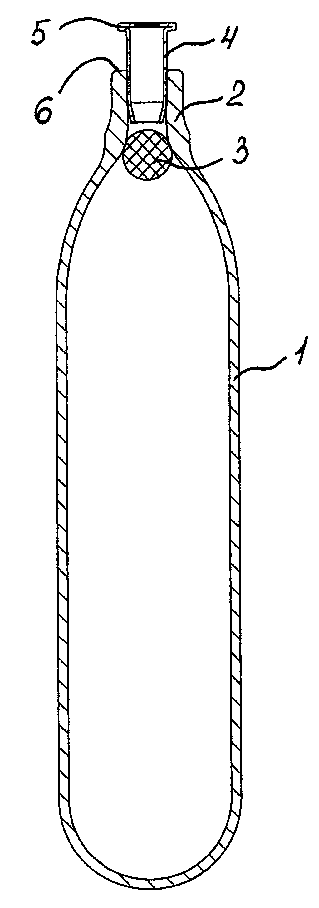
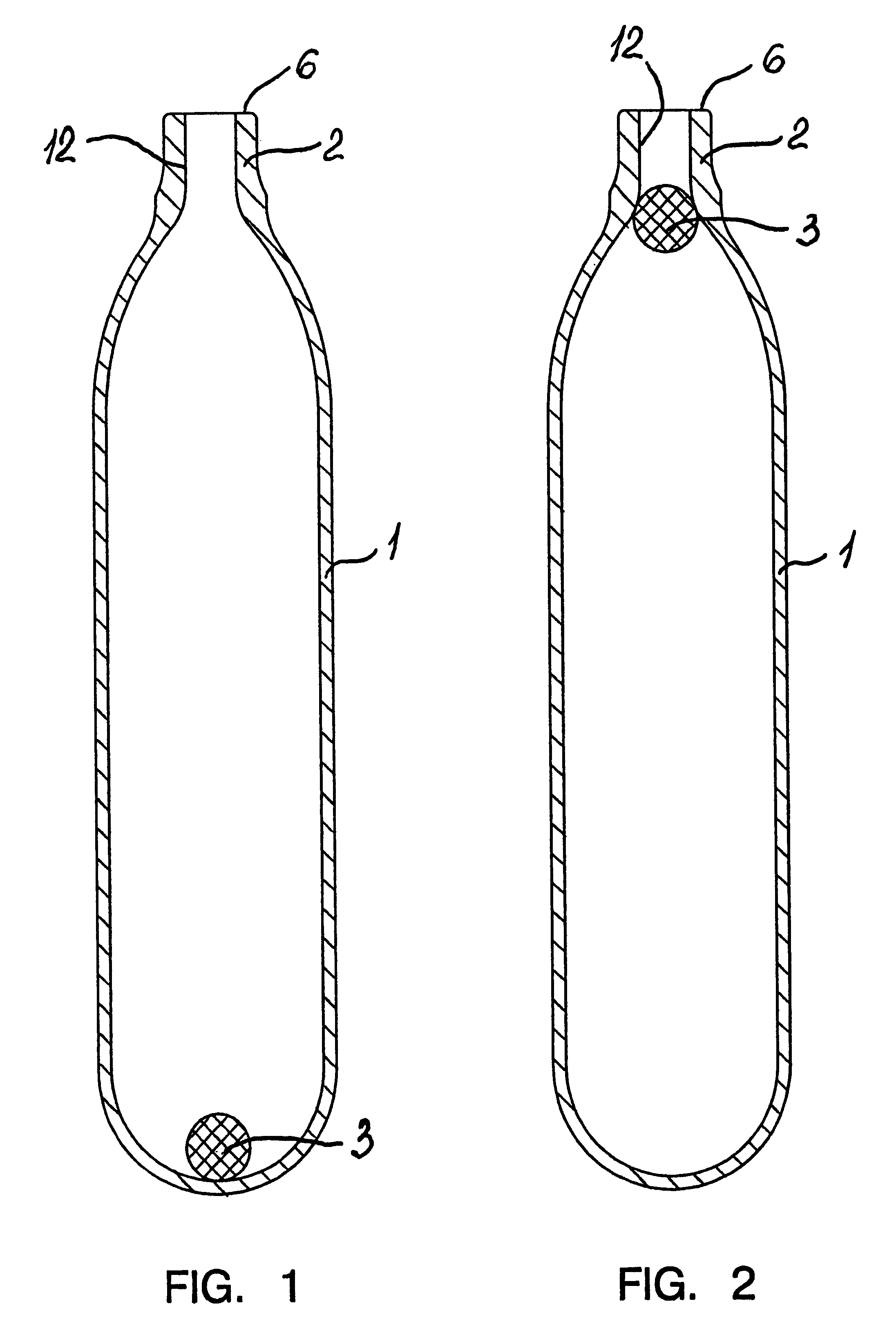
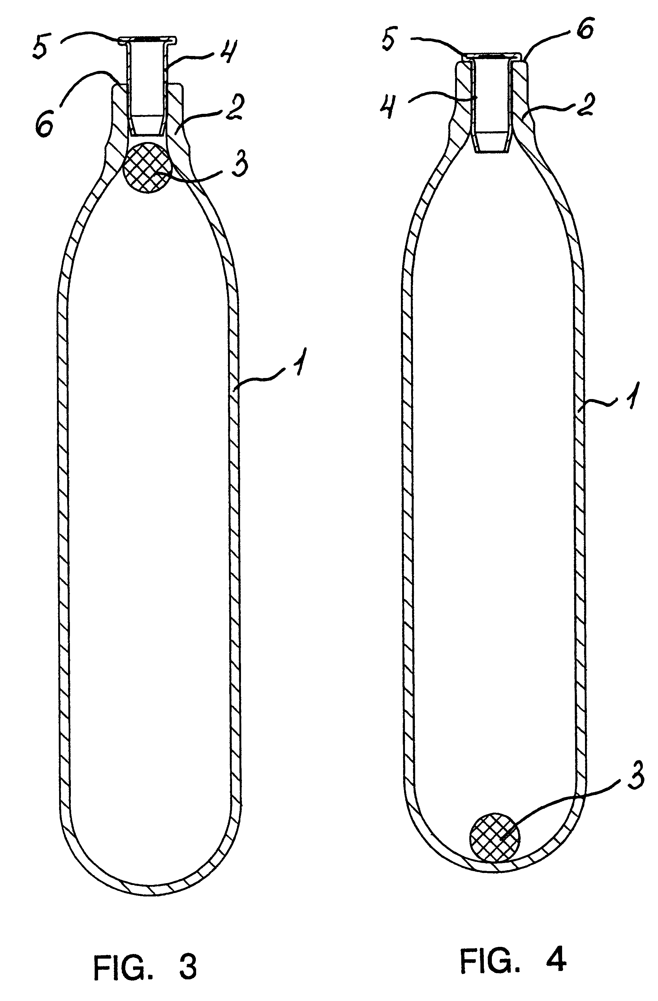
A gas cartridge comprises a body 1 with a neck 2. A ball 3 is disposed inside the Body 1 (FIG. 1). In the neck 2 a cap 4 is located, whose flange 5 is welded to the face 6 of the neck 2 (FIG. 3). In a membrane 7 of the cap 4 a recess 8 is provided to facilitate piercing of the membrane 7. One end of the cap has a chamfer 9 (FIG. 5) or is expanded, e.g., to make a "star" 10 (FIG. 6). The ball 3 can be manufactured from an elastic, resilient material (FIG. 7), from an elastic, resilient material with a metallic powdered filler, or be fully metallic and enclosed in an elastic, resilient envelope 11 (FIG. 8) for snugly fitting against the walls of orifice 12 in the neck 2.

Charging the gas cartridge is carried out in the following manner.

The gas cartridge with the ball 3 disposed preliminarily in the body 1 (FIG. 1) is turned with the neck 2 downward and filled with liquefied gas under a pressure exceeding 10000 gPa through the neck 2. Under the effect of the gas pressure in the cartridg...


PUM

PropertyMeasurementUnit
diameteraaaaaaaaaa
lengthaaaaaaaaaa
densityaaaaaaaaaa

Abstract

A gas cartridge comprises a body 1 with a neck 2. A movable valve made as a ball 3 is disposed inside the body 1. A cap 4 is installed in the neck. The end of the cap 4 can be chamfered or expanded. The ball 3 can be manufactured from an elastic, resilient material, from an elastic, resilient material with a metallic powdered filler or be fully metallic in an elastic, resilient envelope. A method of charging the gas cartridge comprises placing a movable valve inside the body of the cartridge, turning the cartridge with its neck downward and charging the cartridge with a liquefied gas under a pressure, reducing the charging pressure with simultaneous closing of the neck by the movable valve, closing the neck with a cap, pressing-in the cap and welding the flange of the cap to the face of the neck of the cartridge.

Description

FIELD OF THE ARTThe present invention relates to the manufacture and charging with gas of gas cartridges, used, for example, for carbonizing water in siphons, for shooting from air weapons, for gas weapons, for inflating bicycle tyres.STATE OF THE ARTKnown in the art are technical solutions relevant to the structure of gas cartridges to be filled with a gas, for instance, with carbon dioxide gas CO.sub.2, such cartridges being provided with a cover which tightly closes the neck of the cartridge to preclude gas leakage.As the cover, use is made of: a cap (U.S. Pat. No. 2,425,448, Cl. 220-3, 1947) placed onto the neck of the gas bulb and welded to the face portion thereof; a closure (U.S. Pat. No. 2,630,936, Cl. 220-3, 1953) with a cylindrical tubular skirt which is disposed inside the neck portion of the gas container, said closure having a horizontal annular flange welded to the face portion of the neck; a sealing plate (UK Patent Application GB No. 2,045,353, Cl. F16K 17 / 16, 1980) ...

Claims


Application Information

Patent Timeline
Patent Type & Authority Patents(United States)
IPC IPC(8): F17C13/00F17C5/00F17C5/02F17C6/00F17C13/04F17C13/06
CPCF17C5/02F17C13/04F17C13/06F17C6/00F17C2270/07F17C2205/0311F17C2223/0123F17C2270/0736F17C2201/0109F17C2203/0617F17C2205/0323F17C2209/221F17C2209/232F17C2221/013F17C2223/0153F17C2260/036
Inventor SHIPACHEV, ALEKSEI BORISOVICHPETROSYAN, ALEKSEI LVOVICHBAGNYUKOV, SERGEI ANATOLYEVICH
Owner ZAKRYTOE AKTSIONERNOE OBSHCHESTVO GRP ANICS
Why Eureka
Try Eureka