Blood collection and separation system

a separation system and blood collection technology, applied in separation processes, centrifuges, filtration separation, etc., can solve the problems of damage to some red cells, manual process, and device failure to eliminate the centrifugation step described above,

Inactive Publication Date: 2002-04-30
HAEMONETICS
View PDF74 Cites 52 Cited by
  • Summary
  • Abstract
  • Description
  • Claims
  • Application Information

AI Technical Summary

Problems solved by technology

The red cells flowing into the collection bag at the beginning of the collection are, therefore, subject to "anticoagulant shock", which has the effect of damaging some of the red cells.
Although various devices have been developed and marketed whose function is to minimize the amount of labor required in the expression of components from one bag to another, these devices do not eliminate the centrifugation step described above.
It will be appreciated, therefore, that the conventional method of centrifuging and separating components from whole blood is a labor-intensive, manual process.
A central feature of these apheresis devices, however, is that, while they separate blood components at the point of collection, they require that the unwanted components must be returned to the donor.
Such safety mechanisms add cost and complexity to apheresis system equipment and disposables.
In contrast to apheresis systems, conventional whole blood collection systems do not return anything to the donor but, on the other hand, neither are they able to separate blood components at the site of collection.
Preferably, the controller does not permit the rotor to be spun until the needle has been inserted into the interlock device.

Method used


Image

  • Blood collection and separation system
  • Blood collection and separation system
  • Blood collection and separation system

Examples


Embodiment Construction

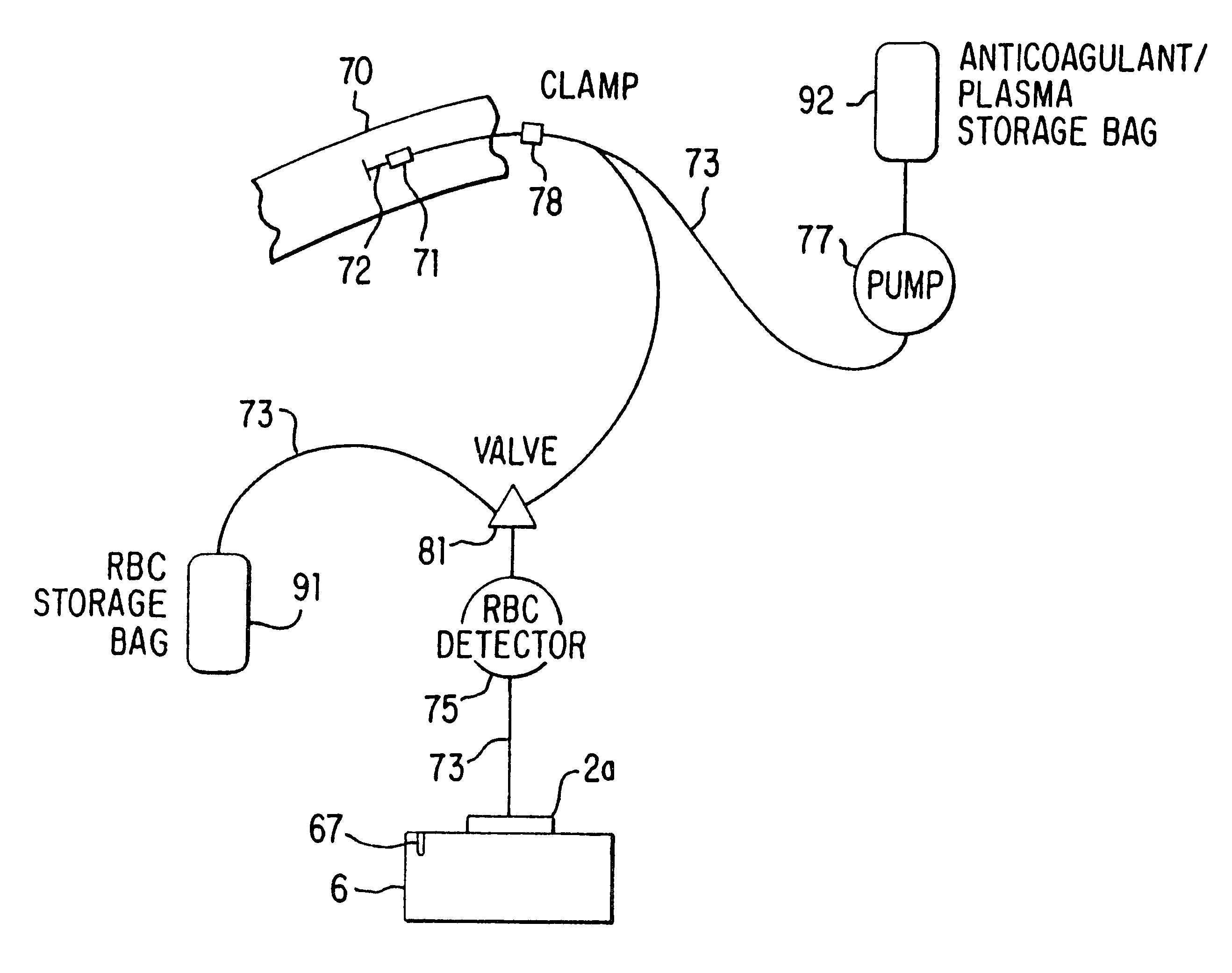
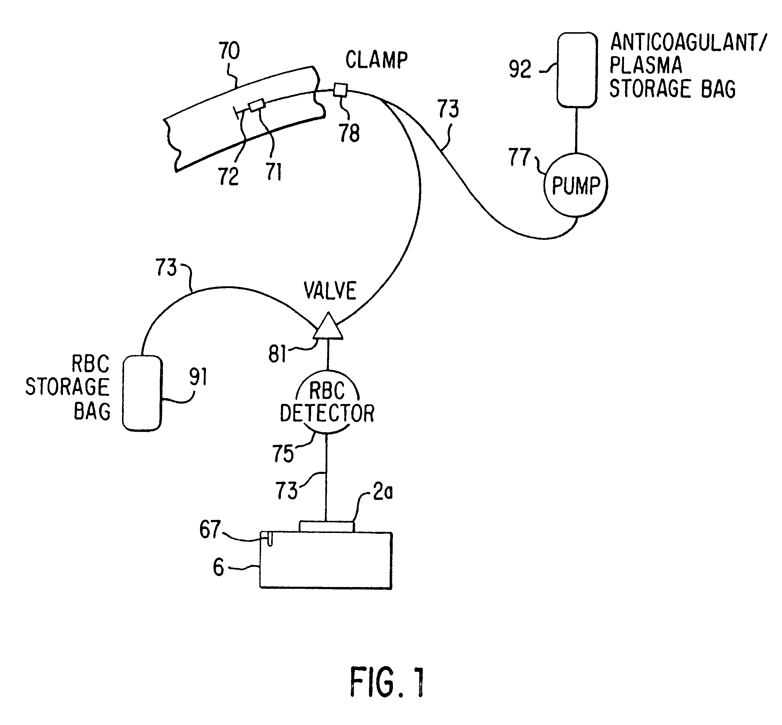
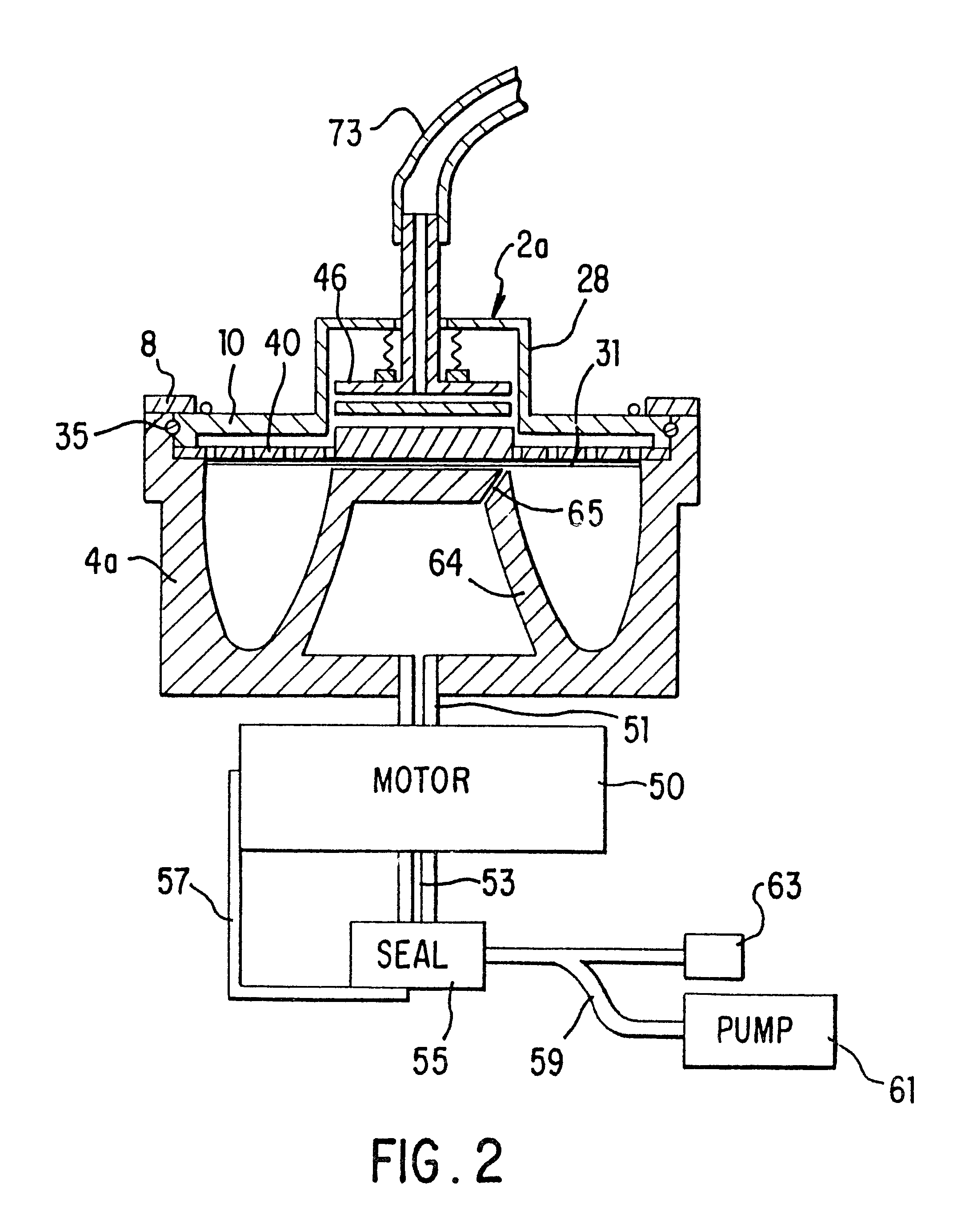
The separator of this invention disclosure, shown schematically in FIG. 1, consists of a sterile, closed-system disposable set in which the blood is collected and processed and a control unit 6 that interfaces with the disposable set and that controls the collection and separation process. One embodiment of the disposable set consists of a needle 72 through which blood is drawn from the donor 70 and a bag 92 containing an anticoagulant such as ACD, CPD or trisodium citrate. This bag 92 serves as the storage container for the plasma or platelet-rich plasma following the processing of the blood by the system. The disposable set also includes a second bag 91, which may contain a red cell preservative solution, and into which the red cells are directed for storage following separation. The set further includes a variable-volume rotor 2a, preferably of the type shown in FIGS. 1-4 of the above-referenced co-pending application Ser. No. 08 / 322,601, now U.S. Pat. No. 5,733,253, although oth...


PUM

PropertyMeasurementUnit
timeaaaaaaaaaa
volumeaaaaaaaaaa
gravityaaaaaaaaaa

Abstract

A system for collecting and processing blood from a donor (70), wherein the system may be compact enough to be located entirely beside the donor's chair, and be able to process the blood while the donor is still resting in the chair after having donated the blood. Thus, the separated blood components (plasma and red blood cells) may be stored in their individual optimum environments immediately after the whole blood is drawn, and the blood does not need to be transported back to a separation laboratory for processing. The system includes a needle (72) (or other cannula-like device) for insertion into a vein of the donor and drawing whole blood therethrough, a variable-volume rotor (2a) for holding the blood after it is drawn, and a motor (50) for spinning the rotor so as to cause the blood to separate into components, for example, plasma and red blood cells. The system also provides for a container for collecting a separated component. In a preferred embodiment two containers are used: the first container (92) for containing an anticoagulant, which is preferably added to the whole blood as it is drawn from the donor, and then for storing the plasma after it has been separated from the red blood cells, and the second container (91) for storing the separated red blood cells. The system further includes tubing (73), which may have valving (81) built into it and which may be acted on externally, so as to direct the blood components in the desired manner.

Description

DESCRIPTION1. Technical FieldThis invention relates to a method of whole-blood collection and the preparation of components therefrom following collection.2. Background ArtIn the conventional method of whole blood collection, a needle is placed in a vein in the donor's arm and whole blood flows by gravity into a bag which holds a quantity of anticoagulant solution, which prevents the blood from clotting. When a unit of whole blood, defined in the United States as 450 milliliters (ml), has been collected, the needle is removed from the vein and the blood bag is set aside for later transfer to the processing laboratory of the blood center.It should be noted that the ratio of anticoagulant to whole blood is approximately one to seven; thus the amount of anticoagulant in the bag is 63 ml. It should also be noted that, while the ratio of anticoagulant to whole blood is one to seven after a full unit has been collected, the ratio of anticoagulant to whole blood is considerably higher than...

Claims


Application Information

Patent Timeline
Patent Type & Authority Patents(United States)
IPC IPC(8): A61M1/36B04B5/04B04B5/00A61M1/00A61M5/145A61M5/148A61M1/02
CPCA61M1/3693A61M1/3698B04B5/0428B04B5/0442A61M1/3696A61M1/0009A61M1/0011A61M5/1483A61M2205/3306A61M2205/3393A61M2205/331A61M1/3692A61M1/67A61M1/62
Inventor KINGSLEY, GORDON F.HEADLEY, THOMAS D.HALPERN, LISE N.
Owner HAEMONETICS
Why Eureka
Try Eureka