
Method for populating substrates with biological cells and populating devices that can be used therefor

Inactive Publication Date: 2002-04-30
BADER AUGUSTINUS
View PDF14 Cites 15 Cited by
  • Summary
  • Abstract
  • Description
  • Claims
  • Application Information

AI Technical Summary

Benefits of technology

A removable insert simplifies handling of the substrate before and after inoculating. When the insert is removed from the reactor, the substrate (that is, for instance, the finished implant) must not be touched or removed from the fixed parts of the reactor, which would be difficultly accessible in the interior of the reactor. This avoids a disadvantageous assembly / disassembly of the substrate being inoculated at fixed, non-removable parts of the housing. This substantially simplified both handling and use after transport to the final user under sterile conditions, such as in the surgery by the physician before implantation. The substrate removed from the reactor with the holding means is freely accessible, remains stabilized for the time being, and can, depending on the holding means, be removed very simply (untied, unclamped, cut loose). This substantially simplifies sterile manipulation of the finished inoculated substrate or implant.
The insert is designed so that the holding means lies at the inside of the container, so that there are two liquid-separating chambers formed on the sides opposite to the held substrate. Work is to be done with separate media or cells in the different chambers. Obviously, one can also work with the same cells and / or media on both sides of the substrate, inner and outer. A significant advantage of the apparatus is derived from the fact that cells (which may be different) can be flushed through repeatedly and that one can alternate between inoculation and perfusion phases without having to open the reactor. It may also be desirable to transfer fluid deliberately through the substrate, especially for organic substrates. The substrate to be inoculated supplements the insert so that one or more chamber dividing walls are formed. The holding means can also be designed to hold multiple substrates, with multiple chambers formed. Each of the chambers formed is preferably provided with liquid inlets and outlets. Likewise the substrate itself can already have multiple chambers, particularly double-walled or multi-walled with lumens between the walls. In this case, further development of the invention can provide that the holding means, preferably at one of the substrate holders, has at least one other inlet or outlet for adding medium, cells, and / or material in at least one internal chamber of this double-waled or multi-walled substrate.
Alternatively, the holder can be folded up or disassembled in a suitable manner so that the substrate held in the holding means can be placed in the inoculating device, and removed from it again, with minimal problem.

Problems solved by technology

With inoculation there is the problem that the substrate must be flushed by the culture medium with the cells, because cells should be transported continuously to the surface, but on the other hand, the flow, or the rolling or pivoting motion within the flask must not be so great that the freshly applied cells are swept off again before they can successfully become established.
There is also the problem that the substrate should be accessible to the cells at all points.
Another disadvantage of previous inoculation methods was that complete confluence of the endothelial cell lawn could not be developed in bioartificial vessels.
Also, mounting and dismounting of the vessel are intricate, as caps must be removed from both ends.
In removal of the finished inoculated vessel there is a danger that the structure will become unsterile because several intricate manipulations are required to remove the vessel from the reactor.
When the insert is removed from the reactor, the substrate (that is, for instance, the finished implant) must not be touched or removed from the fixed parts of the reactor, which would be difficultly accessible in the interior of the reactor.

Method used


Image

  • Method for populating substrates with biological cells and populating devices that can be used therefor
  • Method for populating substrates with biological cells and populating devices that can be used therefor
  • Method for populating substrates with biological cells and populating devices that can be used therefor

Examples


Embodiment Construction

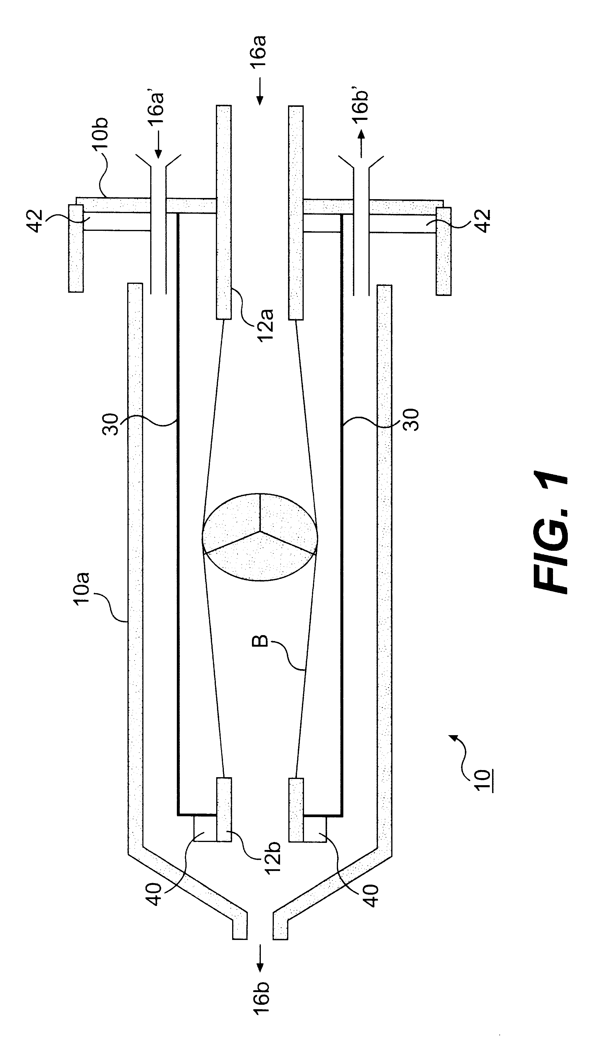
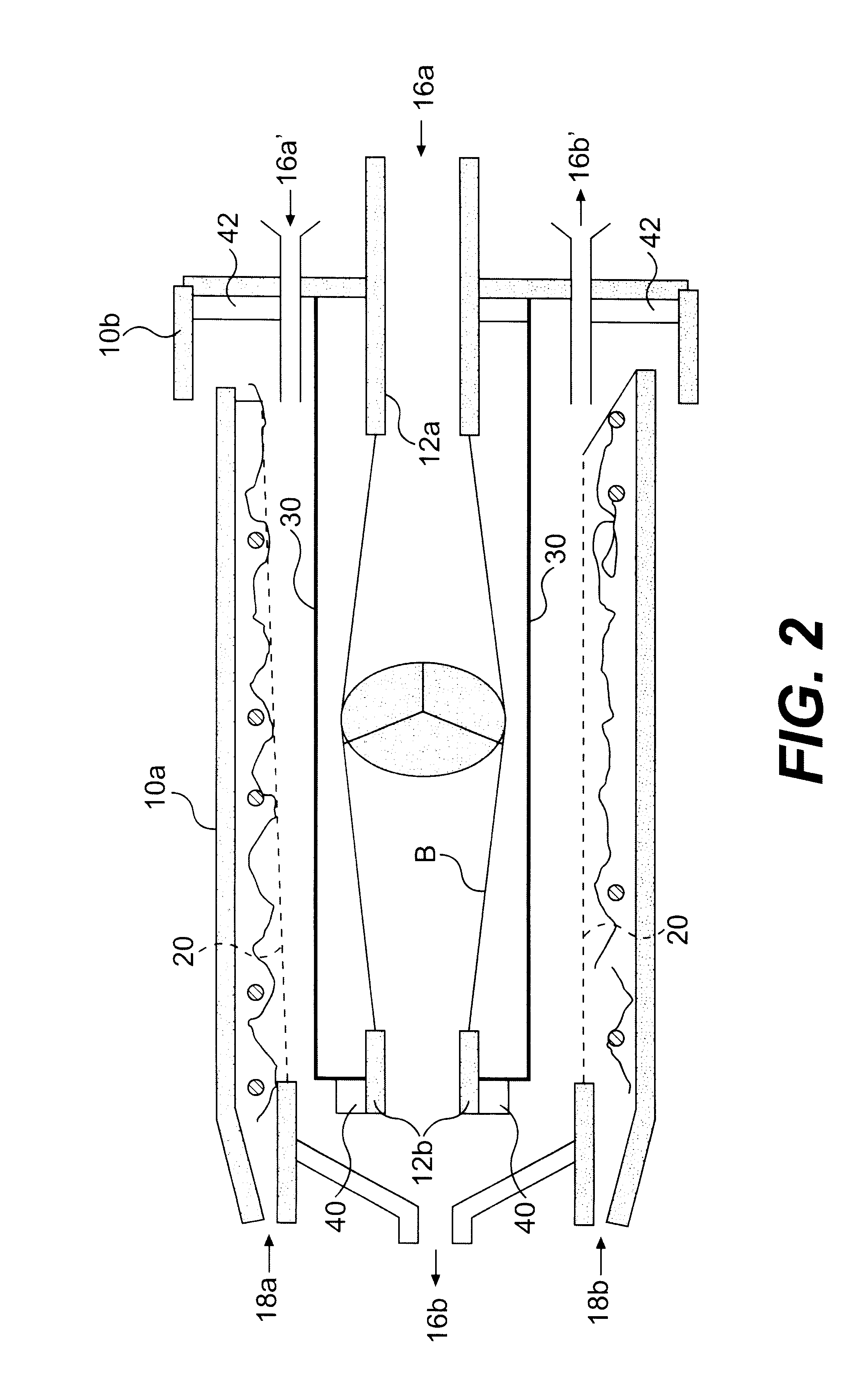
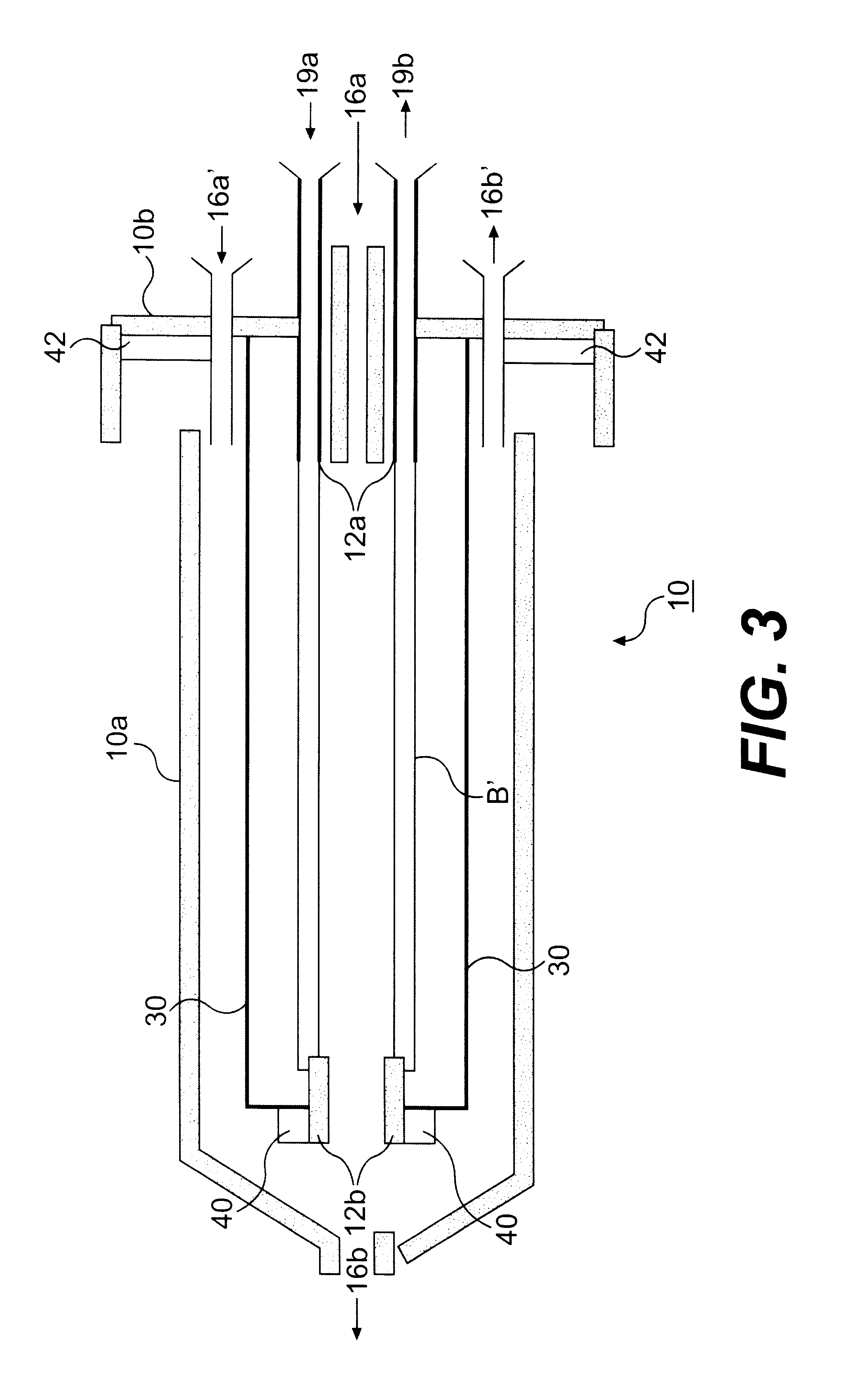
FIG. 1 shows a first example embodiment of the invention in a longitudinal section in an exploded presentation. This is a cylindrical inoculating device designed for inoculating a tubular substrate, designated by B in the drawing. The holder 10 comprises two holder parts 10a, 10b, which are not plugged together in the drawing. The liquid inlet 16a also forms, on the inside, of the device, a first ring-shaped or tubular holder 12a for the substrate. The second ring-shaped holder 12b is connected by rods 30 to the container cover 10b, so that it is firmly connected mechanically to the first holder 12a. The holders 12a and 12b together make up the holding device for the tubular substrate B, a heart valve. When the holder parts 10a and 10b are pushed together, the holder 12b seals against the inner wall of holder part 10a with the sealing ring 40 and the outlet 16b is sealed off. At the same time, the holder 10, made of the holder parts 10a and 10b, is closed and sealed with the seal 42...


PUM


Abstract

The populating method for populating a substrate with living cells provides a population with at least one populating phase and at least one perfusion phase. During the populating phase the substrate can be held in contact with the cell suspension by continuous rotation in various spatial arrangements. The populating device of the invention (10) comprises a rollable container (10a) and a removable insert in it with a means (12) for inserting the substrate being populated, such as a plastic or collagen matrix. The insert is designed so that in interaction with the inserted substrate, two liquid-tight chambers are formed within the container on opposite sides of the inserted substrate, so as to allow separate populating of both sides of the substrate. The container have liquid inlets and outlets (16) and may also have gas inlets and outlets. The rollable populating reactor (10) is inserted into a roller cabinet for certain phases of the populating.

Description

1. Field of the InventionThe invention concerns a method for populating substrates with living biological cells and populating devices that can be used therefor.2. Background DescriptionFor various purposes, it is desired to populate substrates or matrices with cells which should then grow on those substrates. Both substrates of natural origin and those of synthetic origin are considered. Examples of substrates of natural origin might, for instance, be collagen substrates. Synthetic substrates could, for instance, be biologically inert plastics. The substrates to be populated with living cells often have a net-like or sponge-like structure to make it easier for the cells to grow into them.For populating, the cells must be taken to the substrate without being damaged or destroyed; and they must be applied to the substrate in such a manner that growth can occur. In most cases, one tries for a closed cell lawn.The cultured cells, or cells removed elsewhere, are generally in a culture m...

Claims


Application Information

Patent Timeline
IPC IPC(8): C12M3/04C12M3/00C12N1/00C12N5/02C12N5/07C12N5/071
CPCC12M23/48C12M29/10C12M27/10
Inventor BADER
Owner BADER AUGUSTINUS
Learn More