Bus bar system with several bus bars and an installation device with flat connectors

a technology of bus bars and installation devices, applied in the direction of bus bars/wiring layouts, substations/switching arrangement boards/panels/desks, electrical appliances, etc., can solve the problems of connecting contacts and considerable difficulties at the place of employment of switchgear cabinets

Inactive Publication Date: 2002-04-30
RITTALWERK RUDOLF LOH GMBH & CO KG
View PDF8 Cites 53 Cited by
  • Summary
  • Abstract
  • Description
  • Claims
  • Application Information

AI Technical Summary

Benefits of technology

In a further embodiment, the cutouts in the insulating bows can be provided as needed by partial areas which can be broken out and thus it is possible to create the cutout for the contact piece only at the desired location. Then access to bus bars, which are not to be connected, is prevented thus improving insulation toward the connecting elbow, which is not involved.
Contacts between the bus bar and the contact piece can be improved because the contact pieces are designed in a bow shape and form a receiver for the bus bar with their lateral legs.

Problems solved by technology

Thus the connecting contacts can only be made after the installation location of the installation device is set.
However, this presents considerable difficulties at the place of employment of the switchgear cabinet, particularly if the connecting contacts are formed as flat rails for great current strengths.

Method used


Image

  • Bus bar system with several bus bars and an installation device with flat connectors
  • Bus bar system with several bus bars and an installation device with flat connectors
  • Bus bar system with several bus bars and an installation device with flat connectors

Examples


Embodiment Construction

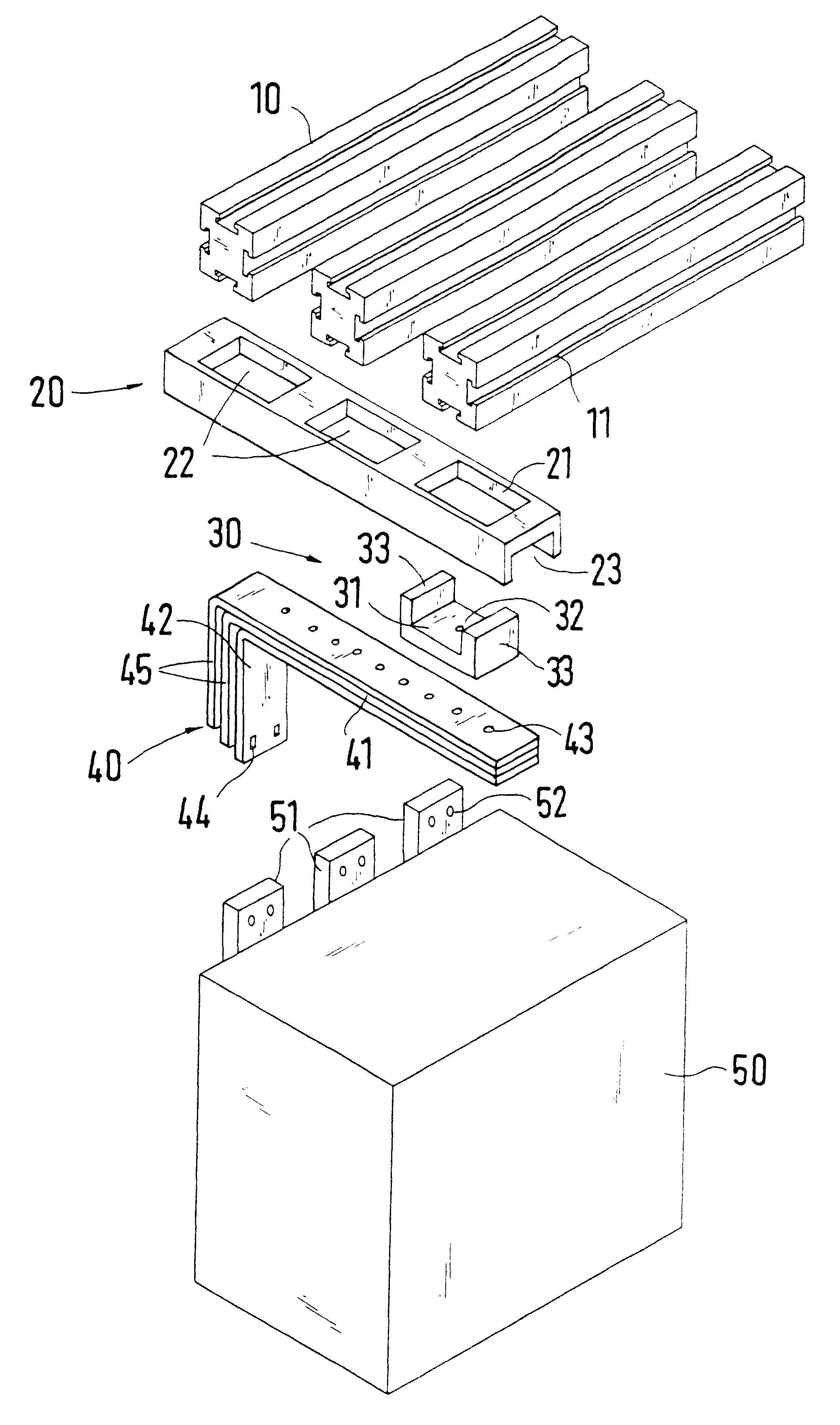
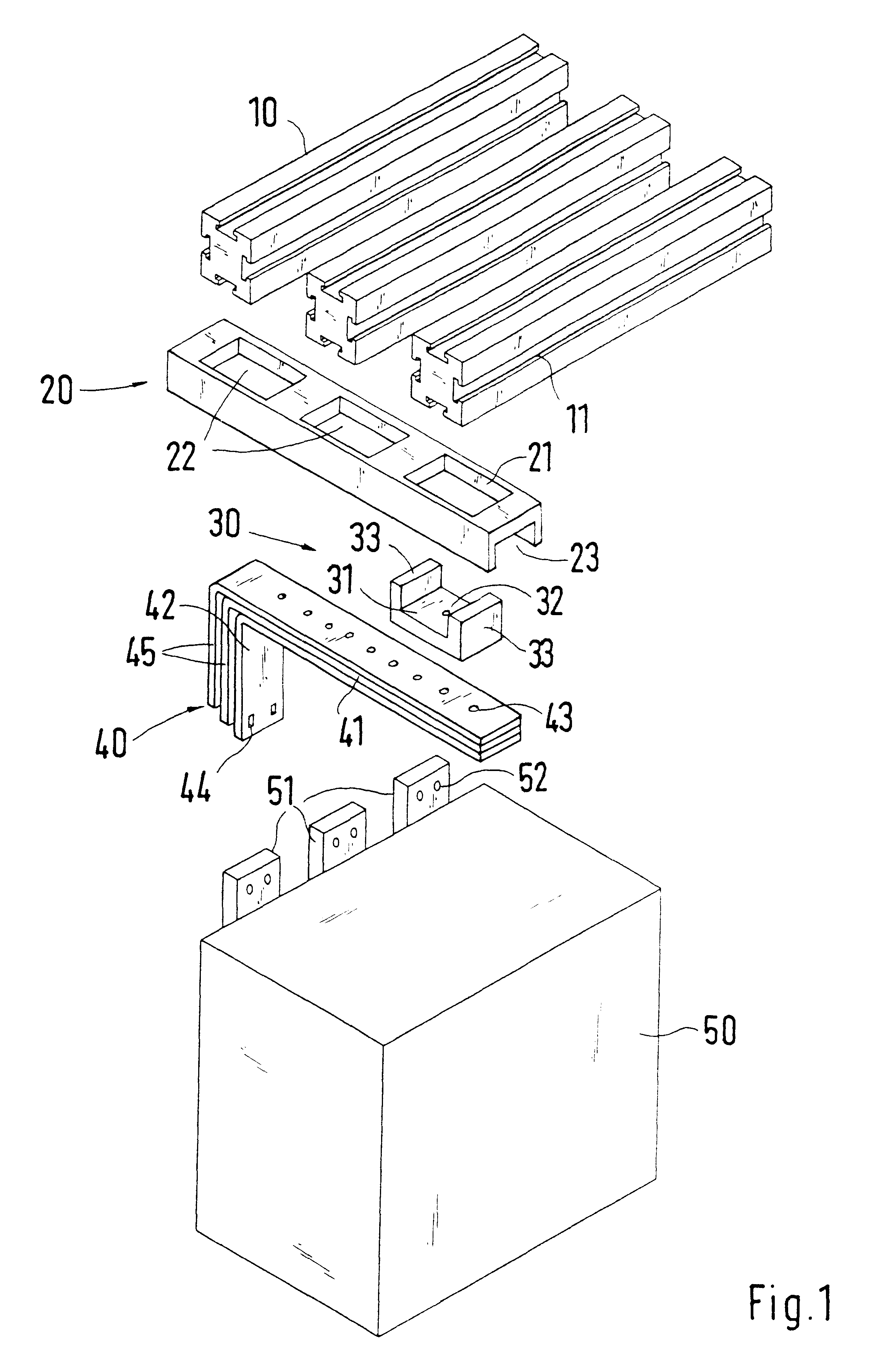
As shown in FIG. 1, three bus bars 10 are arranged at a preset distance from each other in a horizontal connecting plane, wherein a holder, not shown, fixes the bus bars in a fastening plane in the switchgear cabinet. A square cross section and a distance between the bus bars 10 is determined by a maximum current strength. If connecting an electrical installation device 50 having flat connectors 51 with the bus bars 10, the connecting elements are relocated into the vertical connecting plane of the connectors 51 of the installation device 50 which, for example, can be a rotary current power switch. The connection of one phase is explained in view of FIG. 1.

One insulating bow or insulating chassis 20, which can be embodied as a plastic injection-molded part, for example, per phase is attached to an underside of the bus bars 10. The insulating chassis 20 extends transversely to the bus bars 10 and has partial areas 22, which can be broken out to form a cutout 21 in the area of each bu...


PUM


Abstract

A bus bar system having several bus bars spaced apart from each other in a first connecting plane and of an essentially square cross section and having T-shaped connecting grooves cut into all outsides for a connection with electrical installation devices having flat connectors in a second connecting plane, which is arranged perpendicular to the first connecting plane. With specially embodied connecting and insulating elements, it is possible to displace the connecting planes of the bus bars and of the flat connectors of the installations device parallel and perpendicular with respect to each other without it being necessary to perform elaborate matching assembly work at the site.

Description

1. Field of the InventionThis invention relates to a bus bar system having several bus bars, which are spaced apart from each other in a first connecting plane, are of an essentially square cross section and have T-shaped connecting grooves cut into all outsides for a connection with electrical installation devices having flat connectors in a second connecting plane, which is arranged perpendicularly to the first connecting plane.2. Description of Related ArtBus bars and electrical installation devices of this type are preferably used for high current strength and are designed with appropriate large cross sections in current-carrying areas. If, for example, the bus bars are arranged in a horizontal connecting plane of a switchgear cabinet, and if the installation device to be connected which has flat connectors located in one plane is to be installed in the switchgear cabinet in a vertical connecting plane, it is necessary to use specially angled and / or bent off connecting contacts ...

Claims


Application Information

Patent Timeline
Patent Type & Authority Patents(United States)
IPC IPC(8): H02B1/20
CPCH02G5/025H02B1/20
Inventor WAGENER, HANS
Owner RITTALWERK RUDOLF LOH GMBH & CO KG
Why Eureka
Try Eureka