Inductor current synthesizer for switching power supplies

a current synthesizer and switching power supply technology, applied in the direction of electric variable regulation, process and machine control, instruments, etc., can solve the problems of additional circuit loss and sense resistor occupying spa

Inactive Publication Date: 2002-04-30
INFINEON TECH AMERICAS CORP
View PDF7 Cites 81 Cited by
  • Summary
  • Abstract
  • Description
  • Claims
  • Application Information

AI Technical Summary

Problems solved by technology

This method has the drawback of causing additional circuit losses, and the sense resistor occupies space.

Method used


Image

  • Inductor current synthesizer for switching power supplies
  • Inductor current synthesizer for switching power supplies
  • Inductor current synthesizer for switching power supplies

Examples


Embodiment Construction

Assume A / D converter 32 is 10 bits. A / D converters 40 and 42 are 8 bits.

Switching frequency f.sub.s : 300 KHz,

Switching period T.sub.s : 3.33 microseconds.

Inductor L.sub.1 : 800 nH

HF Clock: 10 MHz,

Q2 on resistance R.sub.dson : 6 millions

Input voltage V.sub.in : 20 Volts

Output voltage V.sub.out : 1.3 Volts

I.sub.L1 =20 A

Inductor ripple current: 5 A

n: 10 bits for A / D converter 32 and 8 bits for A / D converters 40 and 42 Input of A / D converter 32 when Q2 is conducting is:

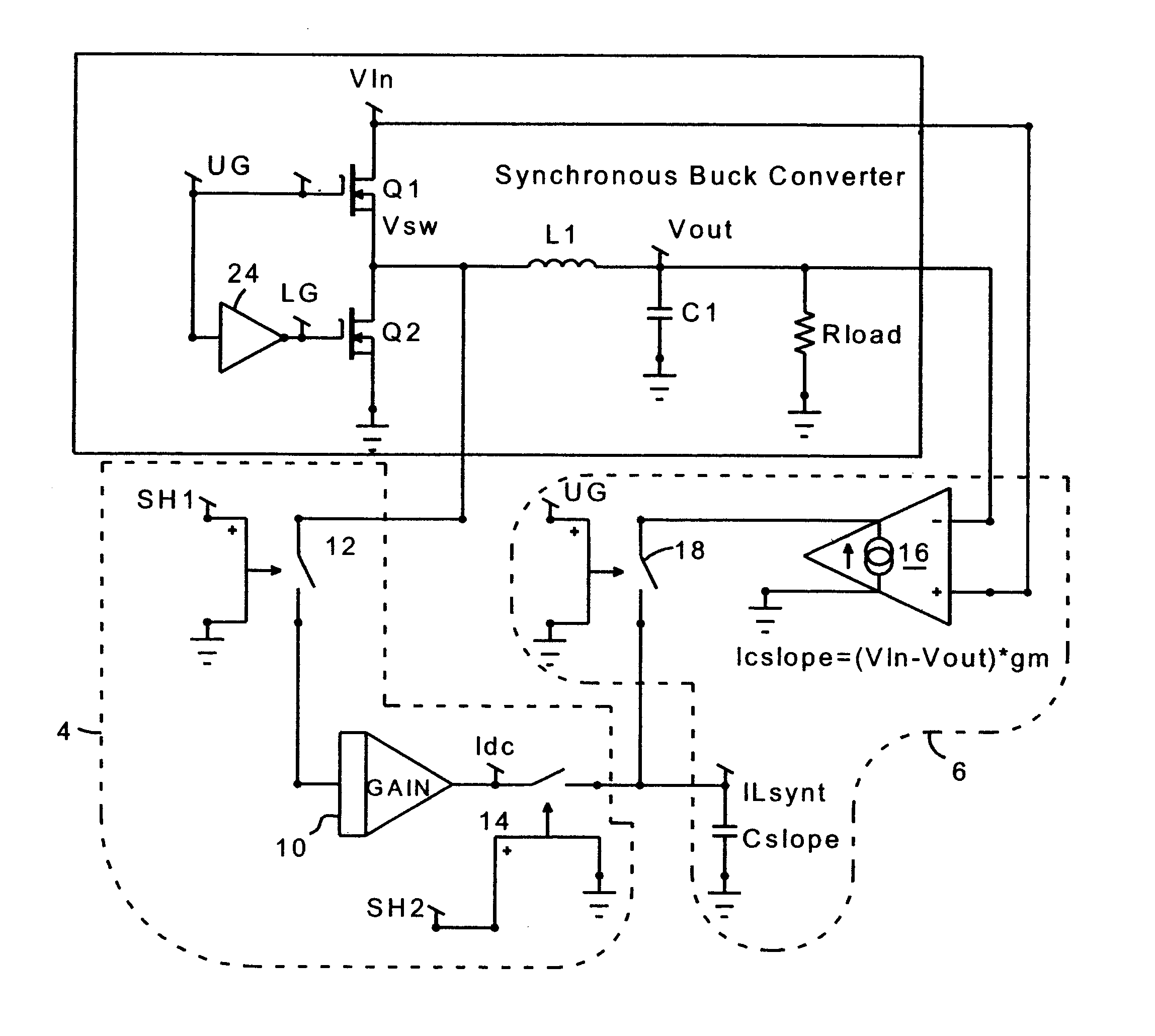
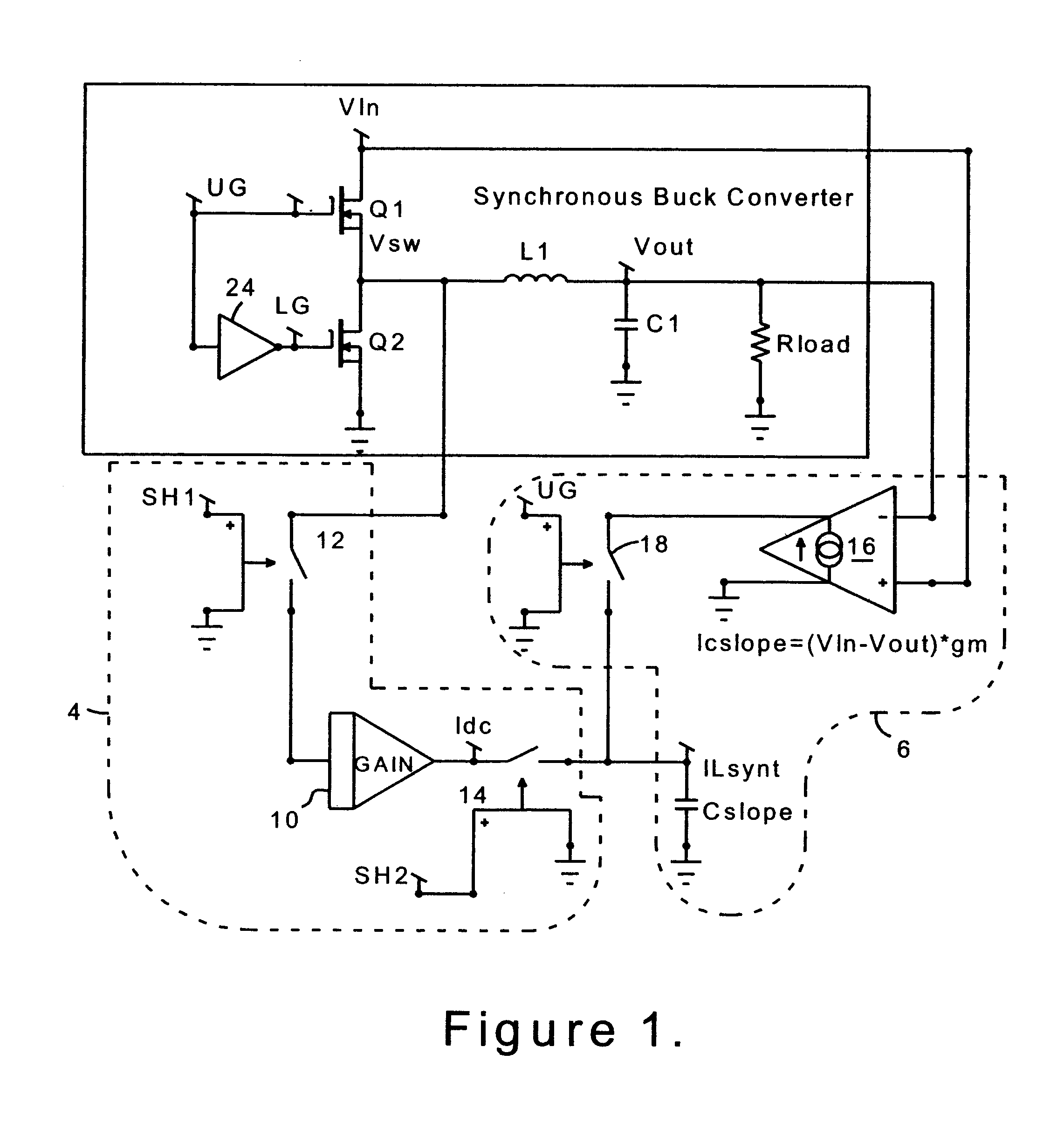
V.sub.sw =R.sub.dson.times.I.sub.L1 (1)

V.sub.sw =0.006*20 A=120 mV

Voltage to Current scaling is 100 mV / A

A / D converter 32 will output 120 counts at 1.024v Full Scale. ##EQU10##

At the ripple generator, 25.5 volts Full Scale for an 8 bit A / D.

Number of counts to maintain 5 A peak to peak ripple:

C.sub.ripple =5A.times.6 count / A=30 counts (2)

Each clock cycle will provide C.sub.clk counts ##EQU11##

Number of counts required to generate 5 A ripple

C.sub.clk =Count / A.times.Count.sub.ch

C.sub.clk =6.times.2.34=14.04 counts

K factor is...


PUM


Abstract

A circuit and method for sensing the inductor current flowing to a load from a switching power supply without using a sense resistor in the path of the inductor current. In a synchronous buck converter topology, the inductor current is derived by sensing the voltage drop across the synchronous MOSFET of the half-bridge and reconstructing the current using a sample and hold technique. A ripple current synthesizer is employed to reconstruct inductor current outside the sample and hold window. The sampled product ILoadxRDSon is used to update the ripple current estimator with dc information every switching cycle. The resulting voltage waveform is directly proportional to the inductor current. The inductor current synthesizer of the present invention can also be used in boost converter, flyback converter and forward converter topologies.

Description

1. Field of InventionThe present invention relates to current mode control of switching power supplies, particularly low voltage power supplies.2. Description of Related ArtCurrent mode power supplies, such as the synchronous buck converter shown in FIG. 1, typically use a resistive element to sense current. This method has the drawback of causing additional circuit losses, and the sense resistor occupies space. Accordingly, it would be desirable to provide a current mode power supply which does not require a resistive element for sensing inductor current.The present invention, in lieu of directly sensing the inductor current with a resistor, derives the inductor current by sensing the voltage drop across the synchronous MOSFET of the half-bridge and reconstructs the current using a sample and hold technique. A ripple current synthesizer is employed to reconstruct inductor current outside the sample and hold window. The sampled product I.sub.Load.times.R.sub.DSon is used to update t...

Claims


Application Information

Patent Timeline
Patent Type & Authority Patents(United States)
IPC IPC(8): H02M3/04H02M3/158H02M3/156H02M3/24
CPCH02M3/156H02M3/1588H01L2924/19043Y02B70/1466H02M2001/0009Y02B70/10H02M1/0009
Inventor OKNAIAN, V. STEPANBROWN, J. STEVEN
Owner INFINEON TECH AMERICAS CORP
Why Eureka
Try Eureka