Multi-valving sample injection apparatus

a valve and sample technology, applied in the field of multi-valve valve apparatus, can solve the problems of difficult automation of devices, large sample excess, and inability to reliably fill the sample loop,

Inactive Publication Date: 2002-05-07
IDEX HEALTH & SCI
View PDF10 Cites 104 Cited by
  • Summary
  • Abstract
  • Description
  • Claims
  • Application Information

AI Technical Summary

Benefits of technology

Accordingly, a rotor valve assembly is provided for a Probe-In-Loop automatic sampling device which enables both Partial-Fill and Complete-Fill injections. Thus, this versatile automatic sampling device enables rapid change of injection volume with zero sample loss and without any hardware changes (i.e., "Partial-Loop Injection" designs), while further offering larger injection volumes with increased volumetric precision (i.e., "Complete-Loop Injection" designs).

Problems solved by technology

Thus, it is frequently necessary to analyze large numbers of samples routinely, even though the samples are available only in small quantities because they are difficult to isolate.
While these designs provide high volumetric precision of the sample (typically in the range of 0.05-0.5% Relative Standard Deviation (RSD)), one problem associated with these "Complete-Loop Injection" systems is that they required an appreciable excess of sample to fill the sample loop reliably.
These devices, however, are difficult to automate because the syringe has to be flushed several times between each injection in order to eliminate cross contamination.
While these PIL automatic sampler designs provide the benefits of zero sample loss and rapid change of sample injection volume without any hardware changes, the injection volumes are relatively small.
Moreover, the volumetric precision of the "Partial-Loop Injection" designs (typically in the range of 0.1-2.0% RSD), while good, is not as high as that of the "Complete-Loop Injection" designs.

Method used


Image

  • Multi-valving sample injection apparatus
  • Multi-valving sample injection apparatus
  • Multi-valving sample injection apparatus

Examples


Embodiment Construction

While the present invention will be described with reference to a few specific embodiments, the description is illustrative of the invention and is not to be construed as limiting the invention. Various modifications to the present invention can be made to the preferred embodiments by those skilled in the art without departing from the true spirit and scope of the invention as defined by the appended claims. It will be noted here that for a better understanding, like components are designated by like reference numerals throughout the various figures.

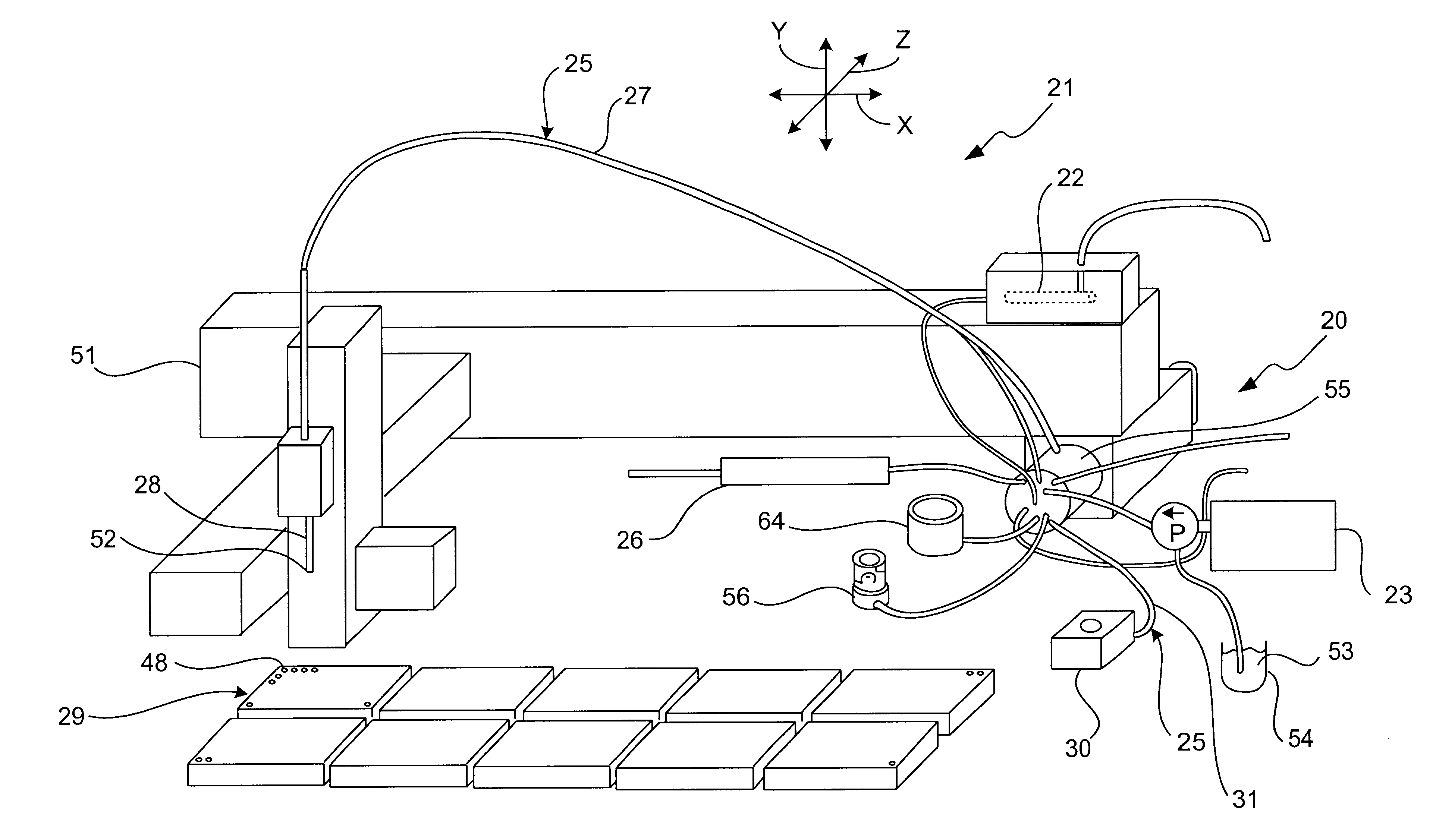
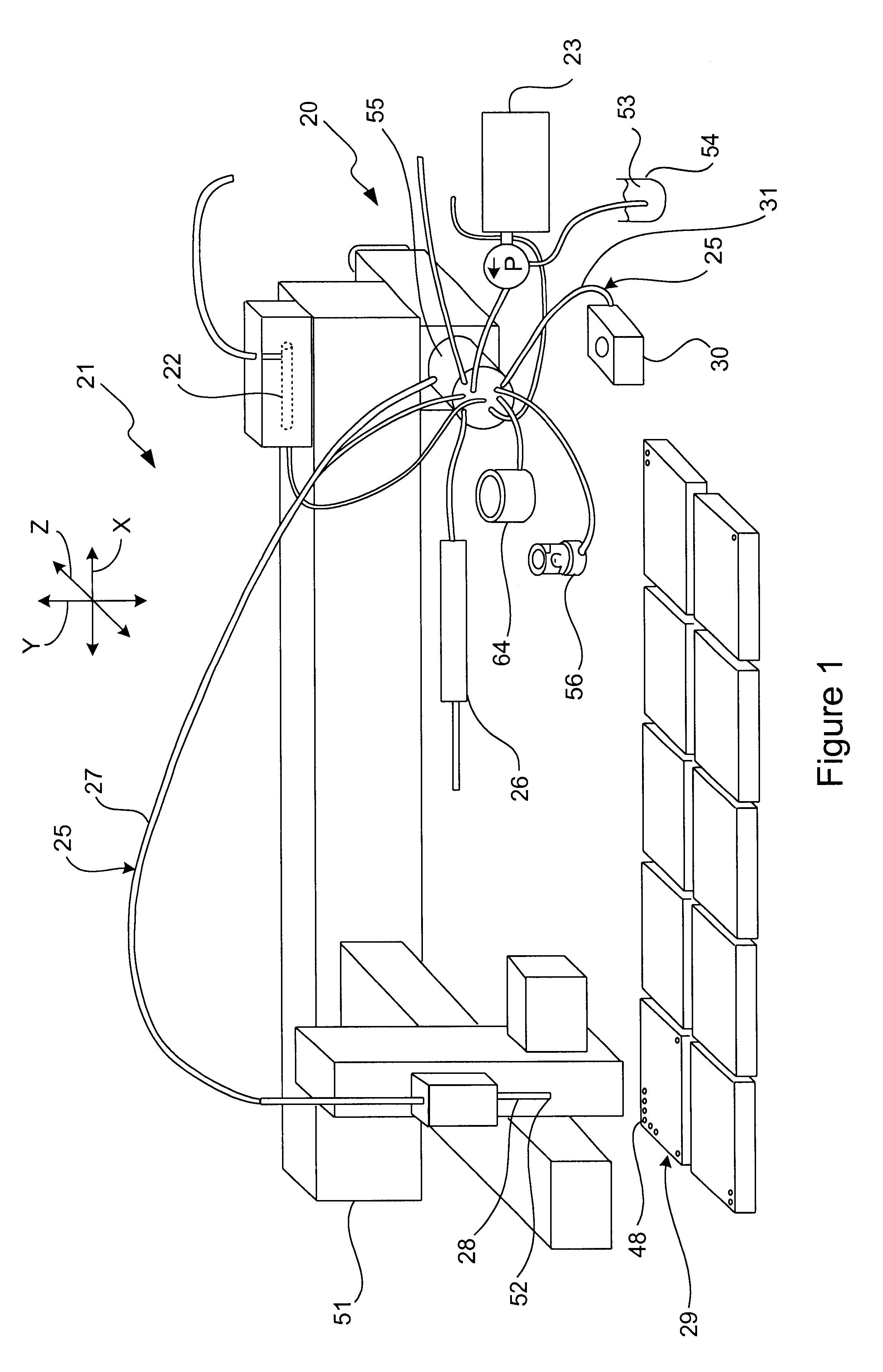
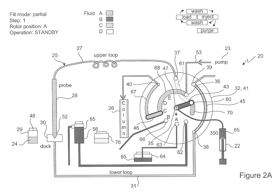
Referring now to FIGS. 1-3, a multi-function valve apparatus, generally designated 20, is provided for use with a Probe-In-Loop (PIL) architecture sample injection assembly 21, having a metering pump 22 and an injection pump 23. The injection pump is configured to direct a Partial-Fill (FIGS. 2A-2J) or a Complete-Fill (FIGS. 3A-3N) of sample 24 into a sample loop 25, and to inject the sample from the sample loop into an analyzing device ...


PUM

PropertyMeasurementUnit
cross-sectional aaaaaaaaaa
volumeaaaaaaaaaa
pressureaaaaaaaaaa

Abstract

A multi-function valve apparatus for use with a Probe-In-Loop (PIL) architecture sample injection assembly which enables both Partial-Fill and Complete-Fill injections. The rotor element is rotatable about a rotation axis relative the stator between: a Load Position, an Overfill Position, and an Injection Position. In the Load Position, a first bridge channel fluidly couples a metering syringe to the sample loop assembly enabling the probe to aspirate one of a discrete volume of sample into the probe, during a Partial-Fill Mode, and a second volume of sample into the probe, during a Complete-Fill Mode. In the Overfill Position, in the Complete-Fill Mode, a second bridge channel fluidly couples a downstream loop portion to a waste port, and the first bridge channel fluidly couples the metering syringe to an upstream loop portion of the sample loop assembly. This enables the metering pump to dispense the sample from the probe into the downstream loop portion and out the waste port to completely fill the downstream loop portion and the second bridge channel with a substantially precise known volume. In the Injection Position, the second bridge channel fluidly couples the downstream loop portion to the analyzing device to inject the sample into the analyzing device, in either the Partial-Fill Mode or and the Complete-Fill Mode.

Description

The present invention relates to sample injection apparatus, and more particularly, relates to multiple function sample valving apparatus for a Probe-In-Loop (PIL) sample injection assembly for liquid chromatographic analysis.High Pressure Liquid Chromatography (HPLC) is a well known conventional technique in which liquid samples to be analyzed are injected under high pressure into a stream of solvent flowing through a chromatographic column. The sample size to be injected is usually several microliters in volume, but it may vary in size from less than 1 microliter up to 100 microliters or more. The pressure of the solvent stream into which the samples are injected may vary from less than 1000 psi up to 6000 psi or more.Advances in Life Sciences, particularly in genomics and proteomics, have greatly increased the potential number of reactions and analyses that must be performed by the biotechnology and pharmaceutical industries. Thus, it is frequently necessary to analyze large numb...

Claims


Application Information

Patent Timeline
Patent Type & Authority Patents(United States)
IPC IPC(8): G01N30/00G01N30/24G01N1/00G01N30/20G01N30/16
CPCG01N35/1097G01N30/24G01N30/20G01N30/16
Inventor NICHOLS, JON A.
Owner IDEX HEALTH & SCI
Why Eureka
Try Eureka