Method of dry printing and painting

a printing method and technology of dry printing, applied in the field of dry printing and painting, can solve the problems of limiting the system from being able to be expanded, the printing system to become mechanically complex, and the inability to handle colorants with relatively large pigment particles, so as to achieve the effect of enhancing the functionality and more flexibility

Inactive Publication Date: 2002-05-14
REVEO
View PDF9 Cites 101 Cited by
  • Summary
  • Abstract
  • Description
  • Claims
  • Application Information

AI Technical Summary

Benefits of technology

Yet another objective is to give printing devices more flexibility and enhance their functionality.
Yet another objec...

Problems solved by technology

This forces the printing system to become mechanically complex and limits the system from being able to be expanded to serve multiple functions such as the case of 3-D printing.
In addition, since the printi...

Method used


Image

  • Method of dry printing and painting
  • Method of dry printing and painting
  • Method of dry printing and painting

Examples


Embodiment Construction

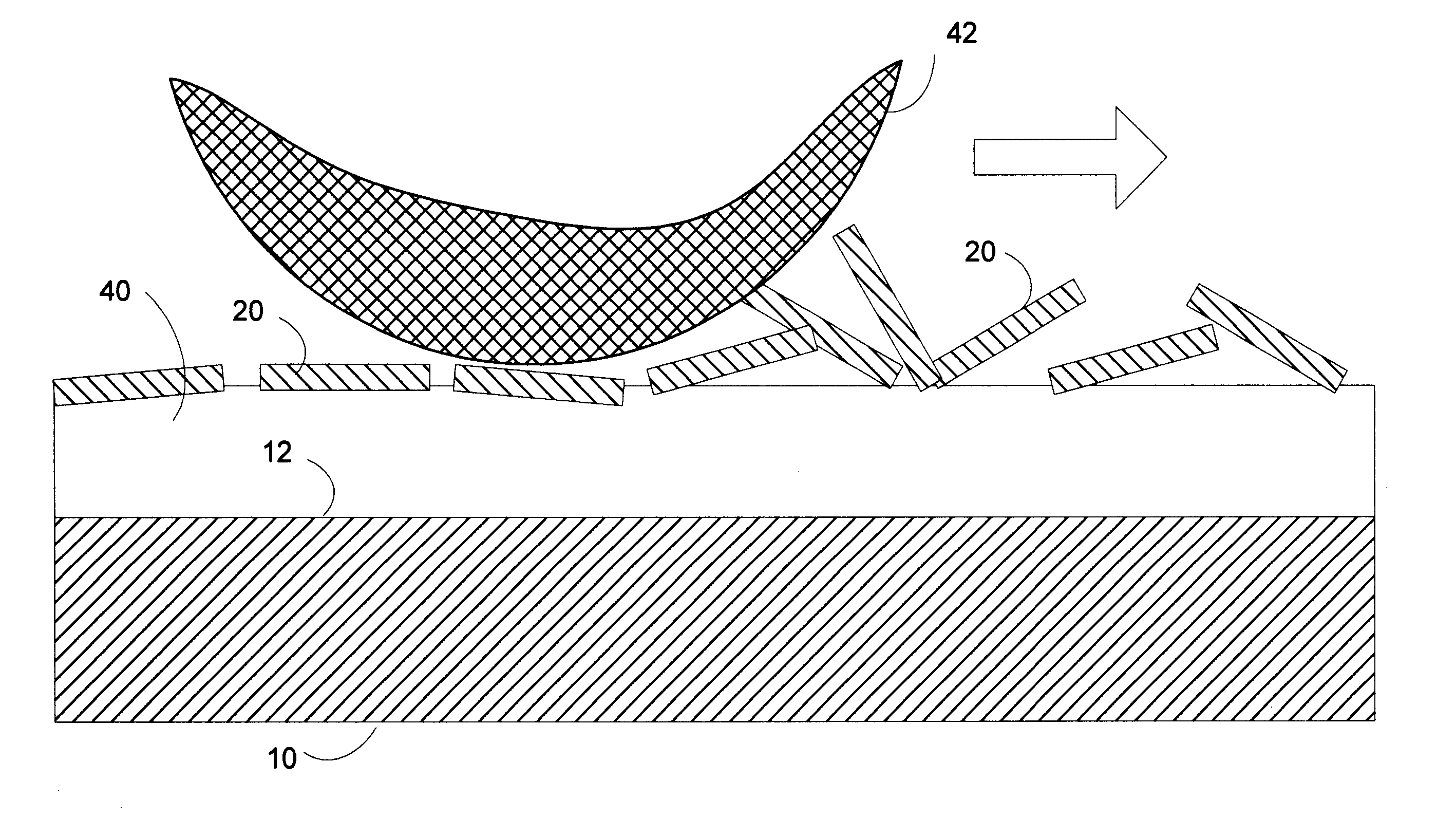
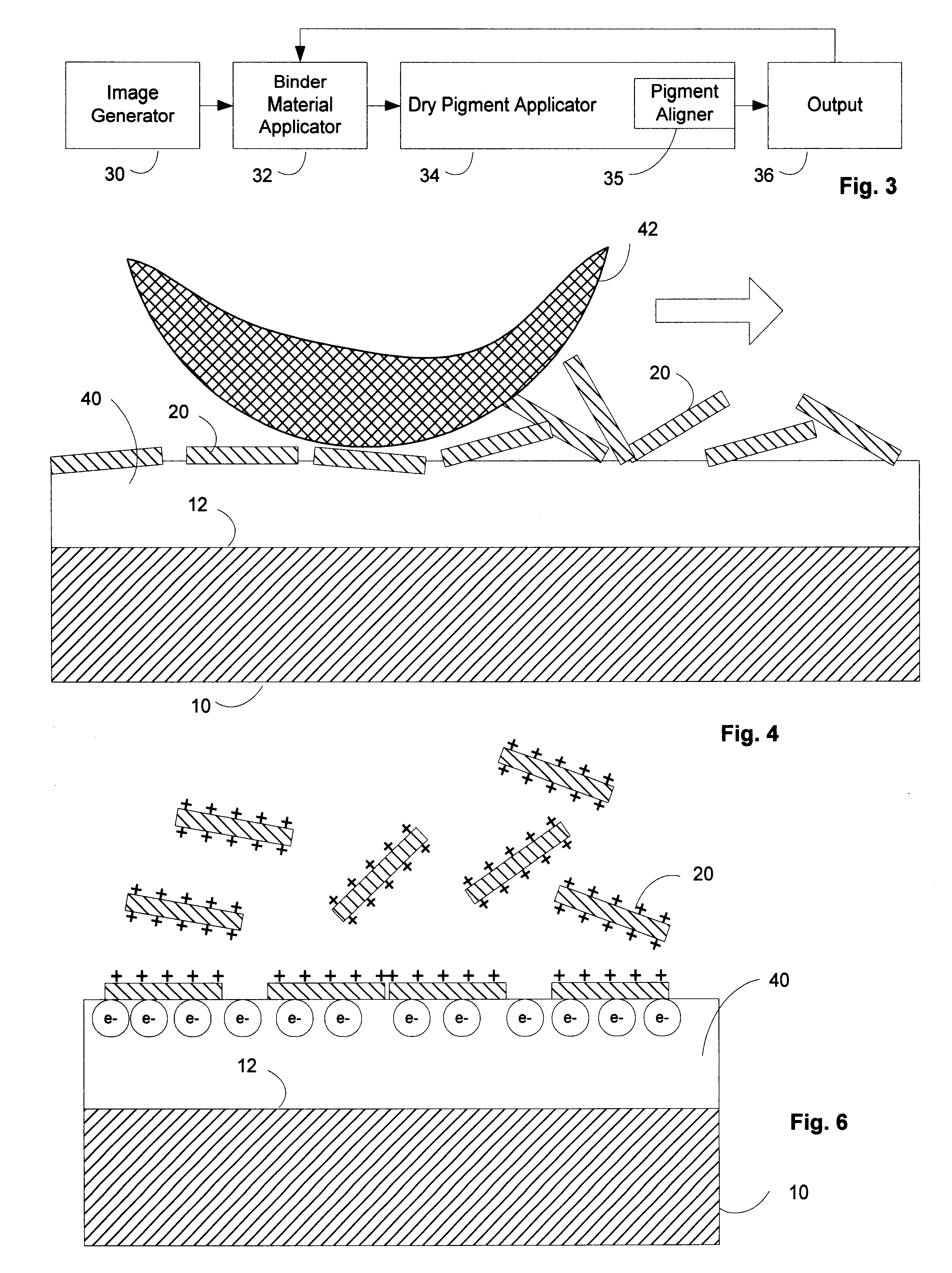
The present invention, termed "Dry Printing Technology" (DPT), enables many new applications to surface. The central part of the new technology is to print an image with an optically clear ink through a single printing head followed by an applying of CLC pigments.

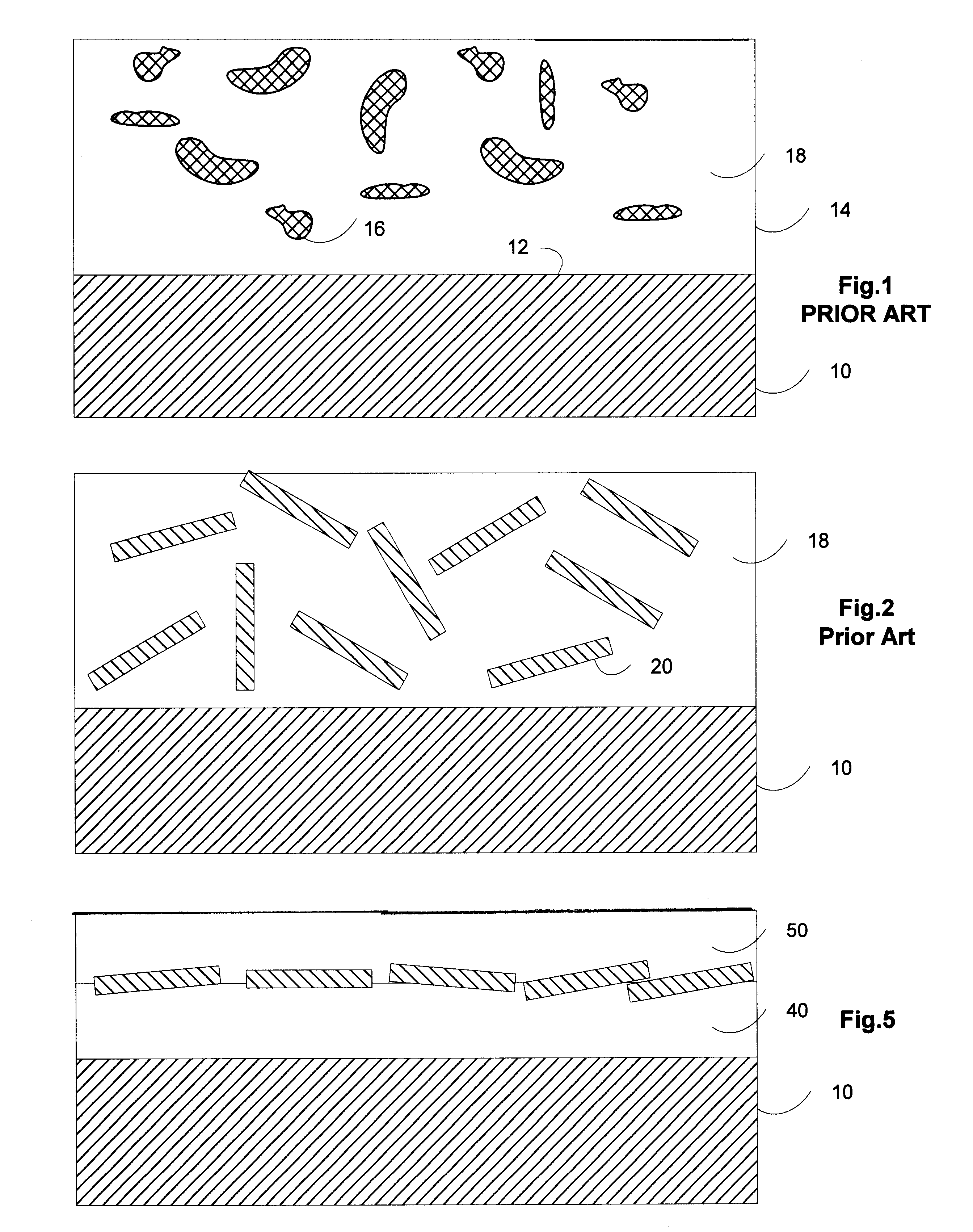
FIG. 1 shows an object 10 having a surface 12 covered with a prior art "paint layer" 14. The paint layer 14 generally comprises pigment particles 16 dispersed in a binder material 18.

FIG. 2 shows a paint layer like FIG. 1 where the pigment material is in the form of flakes 20. The flakes 20 are shown randomly dispersed in the binder material 18. For reflective non metallic pigment particles like CLC flakes, multilayer polymer material flakes, or inorganic multilayer material flakes which have reflectivity by virtue of the interference effect of light reflection from a spatially varying index of refraction, the angle of viewing is critical, and no coherent effect is gained when the eye sees a large collection of pigment part...


PUM

PropertyMeasurementUnit
Particle sizeaaaaaaaaaa
Metallic bondaaaaaaaaaa
Refractionaaaaaaaaaa

Abstract

A method of printing using dry pigments is introduced, wherein a binder material is applied to the surface of an object uniformly or in a pattern, and then dry pigment is applied to the binder material in a pattern or uniformly. The dry pigment sticks to the patterned binder, or the patterned pigment may be bound to the uniform binder, to produce a pattern.

Description

1. Field of InventionThis document describes a technology for painting and image printing that utilizes a simple system with multiple colorants and a single printing head through which the image is printed by a transparent ink or binder. The primary area of interest involves dry pigments of larger molecular weight colorants, such as cholesteric liquid crystal (CLC) pigments, and their diverse applications in modem printing and painting. In addition, new techniques can be easily expanded to serve more functions, such as 3-D stereoscopic image capability.2. Brief Description of the LiteratureBroadband reflecting polarizers were introduced in application Ser. No. 08 / 550,022 (now U.S. Pat. No. 5,691,789) entitled "Single Layer Reflective Super Broadband Circular Polarizer and Method of Fabrication Therefor" by Sadeg M. Faris and Le Li which was filed Oct. 30, 1995. Such broadband polarizers are made by producing a single layer having cholesteric liquid crystal order where the pitch of t...

Claims


Application Information

Patent Timeline
IPC IPC(8): B05D5/06B41M3/00B41M7/00B41M7/02C09D11/10B05D3/12B41M3/14B41M3/06
CPCB05D5/06B41M3/00C09D11/101B41M7/0027B41M7/02B05D3/12B41M3/006B41M3/14B41M3/06B05D1/06
Inventor JIANG, YINGQIULI, LEFARIS, SADEG
Owner REVEO
Why Eureka
Try Eureka