
Method and apparatus for arc welding with melting electrode

a technology of melting electrode and arc welding, which is applied in the direction of arc welding apparatus, welding apparatus, manufacturing tools, etc., can solve the problems of difficult to deal, significantly reduced parameter setting accuracy, etc., and achieve the effect of increasing the power of the arc, reducing the fusion rate, and increasing the length of the ar

Inactive Publication Date: 2002-05-14
ESAB AB
View PDF13 Cites 11 Cited by
  • Summary
  • Abstract
  • Description
  • Claims
  • Application Information

AI Technical Summary

Benefits of technology

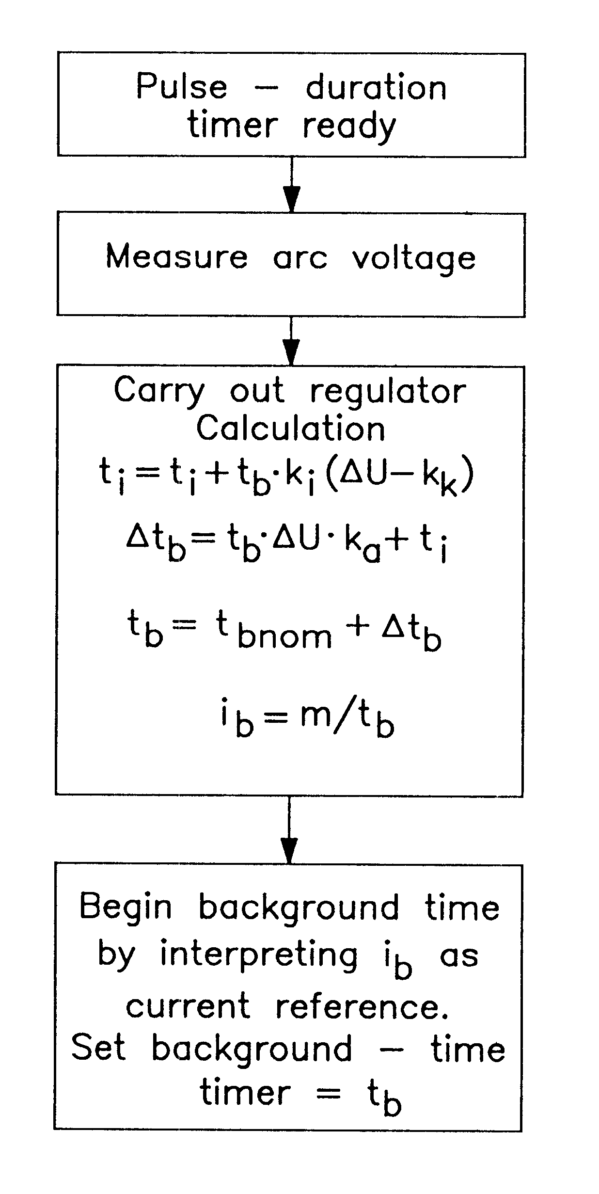
As a result of the arc pressure, the molten pool is always in motion. When the arc length is shortened, the electrode end will briefly come into contact with the moving molten pool. These brief contacts do not normally lead to any material transfer, however, as the drop is retained on the electrode by forces directed towards the electrode. These repellant forces may, for example, be connected with the vaporization of principally oxidized alloying materials from the surface of the fusible electrode end. By detecting these brief short-circuits and, on the basis of their occurrence, increasing the power for the arc, the fusion rate and thus the arc length are increased. In this way, the procedure and the arrangement according to the invention make it possible to weld with minimum arc length without ending up in the short-arc range.
The method facilitates considerably synergic pulsing with a very short arc and thus makes possible virtually splash-free welding, even of thin plate. The method also offers considerably reduced sensitivity for parameter-setting accuracy and thus makes possible welding in situations that are very difficult to deal with.

Problems solved by technology

The method also offers considerably reduced sensitivity for parameter-setting accuracy and thus makes possible welding in situations that are very difficult to deal with.

Method used


Image

  • Method and apparatus for arc welding with melting electrode
  • Method and apparatus for arc welding with melting electrode
  • Method and apparatus for arc welding with melting electrode

Examples


Embodiment Construction

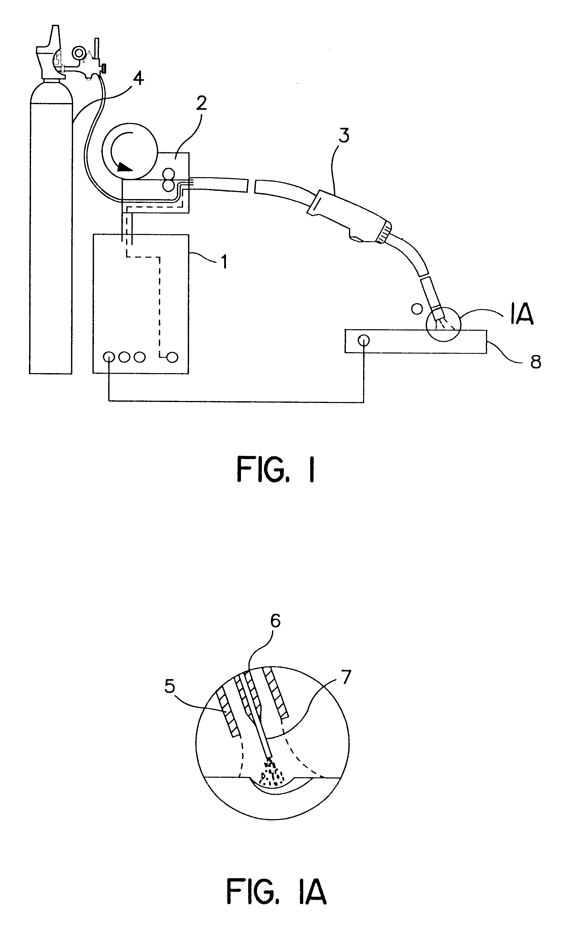
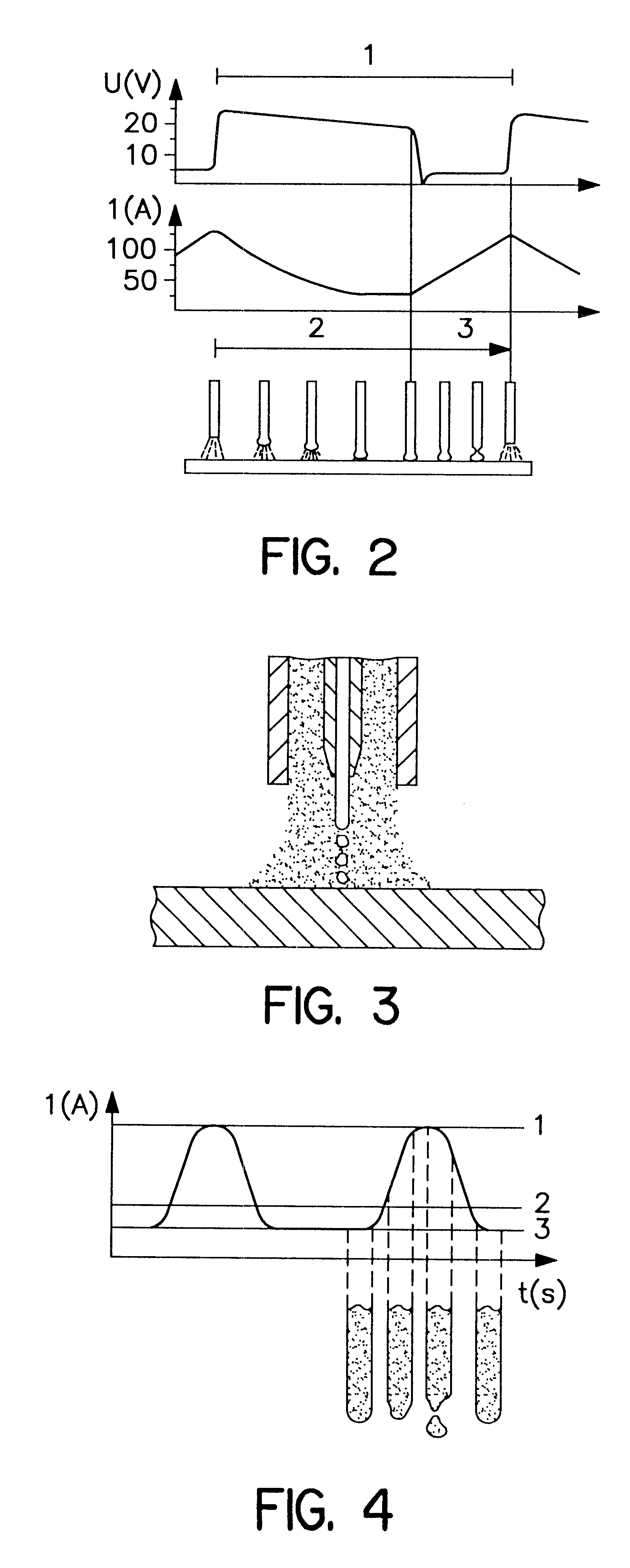
FIG. 1 shows an arrangement for MIG / MAG welding. This arrangement comprises a pulsed welding-current source 1 and a wire-feed mechanism 2. The arrangement also comprises a welding gun and a gas container 4 connected thereto. The welding gun comprises a front nozzle comprising an outer pipe 5 through which the gas is guided out, and, arranged centrally in this pipe, an inner pipe, the contact nozzle 6, through which the electrode 7 is guided. The electrode 7 and the workpiece 8 are connected in a conventional manner to the welding-current source 1 so that a potential difference is formed between them. The arrangement is controlled so that the material transfer from the electrode to the workpiece takes place essentially without short-circuiting drops (FIG. 4). This is effected by the welding current being periodically increased to a pulse current of such size and duration that the current density in the electrode causes sufficient electromagnetic forces in order to separate one drop f...


PUM

PropertyMeasurementUnit
Timeaaaaaaaaaa
Poweraaaaaaaaaa
Currentaaaaaaaaaa

Abstract

The invention comprises a method and an arrangement for pulsed gas metal-arc welding with an electrode fed to the welding site continuously at a given rate, the fusion conditions being adapted in such a manner that the material transfer from the electrode (7) to the workpiece (8) takes place essentially without short-circuiting drops by the welding current being periodically increased to a pulse current of such size and duration that the current density in the electrode causes sufficient electromagnetic forces in order to separate one drop for each pulse, and where the arc length is stabilized by regulating the power supply for the arc by means of a regulator mainly on the basis of a measured arc voltage, characterized in that short-circuiting of the arc is detected as arc-voltage decreases and / or current increases, and in that the fusion power supplied is increased by the arc-length regulator being given an additional increase for each short-circuit detected.

Description

The present invention relates to a method and an arrangement for correcting, during pulsed gas metal-arc welding with a continuously fed electrode and material transfer from the electrode to the workpiece essentially in the form of non-short-circuiting drops, the power supply for the welding process on the basis of the occurrence of brief short circuits between the electrode and the workpiece. The correction is carried out in a regulating process in which the power supply is in the main regulated depending on the arc voltages so that a constant arc length is obtained. The correction facilitates welding using a very short arc.In gas metal-arc welding using a continuously fed fusible electrode, usually called MIG / MAG welding, the workpiece is heated principally by the arc. The electrode is heated on the one hand by the power generated when the welding current flows through the electrode projection, that is to say the free electrode end between the contact nozzle, where the current tra...

Claims


Application Information

Patent Timeline
IPC IPC(8): B23K9/09
CPCB23K9/092
Inventor ANG.BERG, PERBENGTSSON, LARS
Owner ESAB AB
Learn More