Belt driven roller conveyor

a belt drive and roller conveyor technology, applied in the direction of roller-ways, transportation and packaging, etc., can solve the problems of belt cord breakage, limited length of round closed loop belts, and the need for partial disassembly of the replacement bel

Inactive Publication Date: 2002-05-21
DEMATIC
View PDF22 Cites 23 Cited by
  • Summary
  • Abstract
  • Description
  • Claims
  • Application Information

AI Technical Summary

Problems solved by technology

The round closed loop belts, however, are limited in length.
Furthermore, because of their geometry, as the round or circular belts are driven in their closed loop, the round belts may twist which over time may cause the belt cords to break.
Moreover, due to the conventional configurations of the round belt driven systems, replacement of these belts requires partial disassembly of the conveyor.
Replacement of these belts, therefore, may impose a significant cost on the user of the conveyor.
However, the round belts still may exhibit short life spans.
However, use of link belts has not been without difficulties.
However, the link belt driven systems exhibit significantly increased noise due to the vibration of the belt and other components as the belt's undulating surface contacts the rollers.
The noise can be extreme.

Method used


Image

  • Belt driven roller conveyor
  • Belt driven roller conveyor
  • Belt driven roller conveyor

Examples


second embodiment

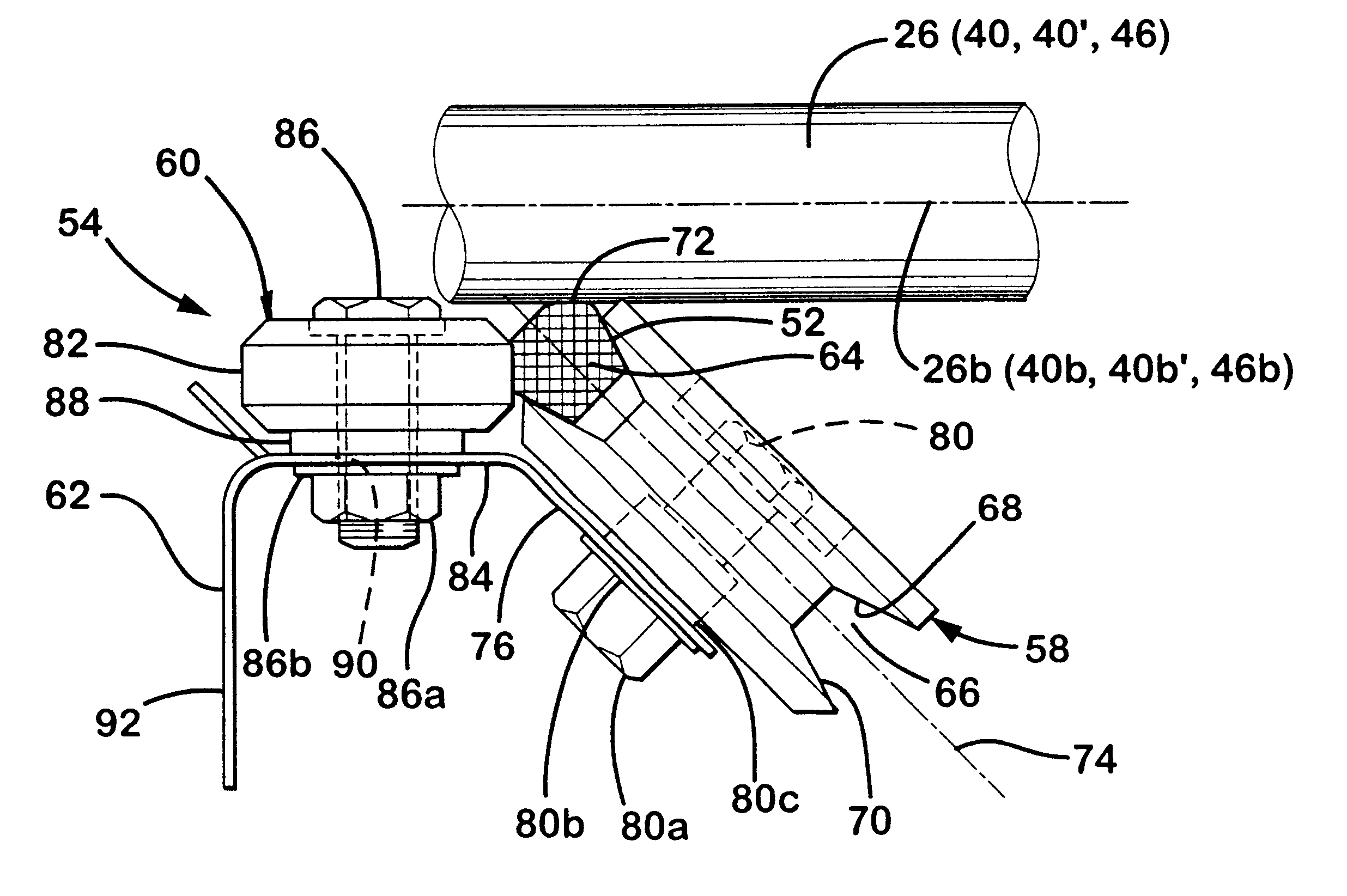
Referring to FIGS. 13-19, belt 152 is illustrated. Similar to belt 52, belt 152 includes a base 164, a rounded upper or outer sure 170 and a driving edge 172. As best seen in FIG. 15, edge 172 is offset from belt axis of symmetry 154a and provides a continuous linear driving surface for driving the rollers. Preferably, edge 172 is offset at an angle of 35 to 45 degrees from surface 170 and, most preferably, about 40 degrees. In is embodiment, belt 152 comprises a link belt configuration and includes a plurality of link members 154. Each link member 154 includes a body portion 156 and a connector portion 158 which projects from body portion 156 for coupling link member 154 to second and third link members 154' and 154". It should be understood from FIGS. 13-15, each link of link belt 152 couples to second and third links except the last link which couples to ate first and second links to create a desired length of closed loop belt 152. Body portion 156 includes first and second elong...

first embodiment

While several forms of the invention have been shown and described, other forms will now be apparent to those skilled in the art. For example, other drive arrangements may be used to drive the belts preferably in a manner that maintains the orientation of the belt to minimize twisting. In addition, as mentioned in reference to the first embodiment, the conveyor sections may have other frame configurations. Furthermore, on the straight runs of the junction conveyor section one or more lateral restraints may be omitted from the spring pulley assemblies. Moreover, the general mounting details and configurations may be varied as desired without departing from the scope of the invention. The embodiments of the invention shown in the drawings are not intended to limit the scope of the invention which is defined by the claims which follow.


PUM


Abstract

A roller conveyor belt driver system for a roller conveyor includes a closed loop belt having a continuous driving surface and a non-circular base and a plurality of pulleys which support and engage said non-circular base for at least partially laterally restraining the belt from rotation. A first group of pulleys are constructed and arranged to position the belt in non-orthogonal orientation with respect to the rollers of the conveyor for contacting one or more rollers with the driving surface of the belt. Optionally, the belt driver system includes a lateral restraint associated with a respective pulley of the first group of pulleys to urge the belt to remain engaged with the respective pulley to prevent twisting of the belt and, therefore, increase the life of the belt. For example, the lateral restraint may comprise a bearing which is positioned adjacent the respective pulley and which contacts the belt to maintain the belt in proper orientation in the pulley. In one form, the belt comprises a link belt, which is formed from a plurality of interlocking links, which permits the belt to be easily removed for service or replacement.

Description

TECHNICAL FIELD AND BACKGROUND OF THE INVENTIONThe present invention relates to a conveyor and more particularly to a belt driven roller conveyor. The invention can be used with straight or curved roller conveyors.Conventional roller conveyors are often belt driven either by a plurality of intermediate O-ring belts associated with each of the respective rollers or a single continuous closed loop direct drive belt which extends over a discrete length of the conveyor section. Heretofore, one type of closed loop drive belt that has been used on roller curves has a round cross-section comprising a rubber-covered cord. The round closed loop belts, however, are limited in length. Consequently, the belt drive system configuration is dictated by the available lengths of the belts. Furthermore, because of their geometry, as the round or circular belts are driven in their closed loop, the round belts may twist which over time may cause the belt cords to break. Moreover, due to the conventiona...

Claims


Application Information

Patent Timeline
Patent Type & Authority Patents(United States)
IPC IPC(8): B65G13/07B65G13/02B65G13/071B65G13/08
CPCB65G13/07
Inventor NGUYEN, THANH V.SCHUITEMA, DENNIS J.
Owner DEMATIC
Why Eureka
Try Eureka