Radio communication equipment

a technology of radio communication and equipment, applied in the direction of substation equipment, electrical equipment, demodulation, etc., can solve the problems of increasing power dissipation and existent problems, and achieve the effect of high speed withou and any increase in power dissipation of frequency synthesizers

Inactive Publication Date: 2002-05-21
KK TOSHIBA
View PDF7 Cites 47 Cited by
  • Summary
  • Abstract
  • Description
  • Claims
  • Application Information

AI Technical Summary

Benefits of technology

It is an object of the present invention to provide radiocommunication apparatus which permits two receiving systems to be operated simultaneously or to be switched at a high speed without any increase in power dissipation of frequency synthesizers.

Problems solved by technology

However, operating the two frequency synthesizers results in an increase in power dissipation.
In particular, this is a serious problem for mobiles subject to constraints in continuous operating time.
This problem likewise arises in the case where each of two transmission systems has its corresponding frequency synthesizer.
In addition, this problem is existent not only in such single superheterodyne radiocommunicatior apparatus as shown in FIG. 7 but also in double superheterodyne radiocommunication apparatus or TDD (Time Division Duplex)-based radiocommunication apparatus that is equipped with two frequency synthesizers for simultaneous reception of signals in two bands.

Method used


Image

  • Radio communication equipment
  • Radio communication equipment
  • Radio communication equipment

Examples


Embodiment Construction

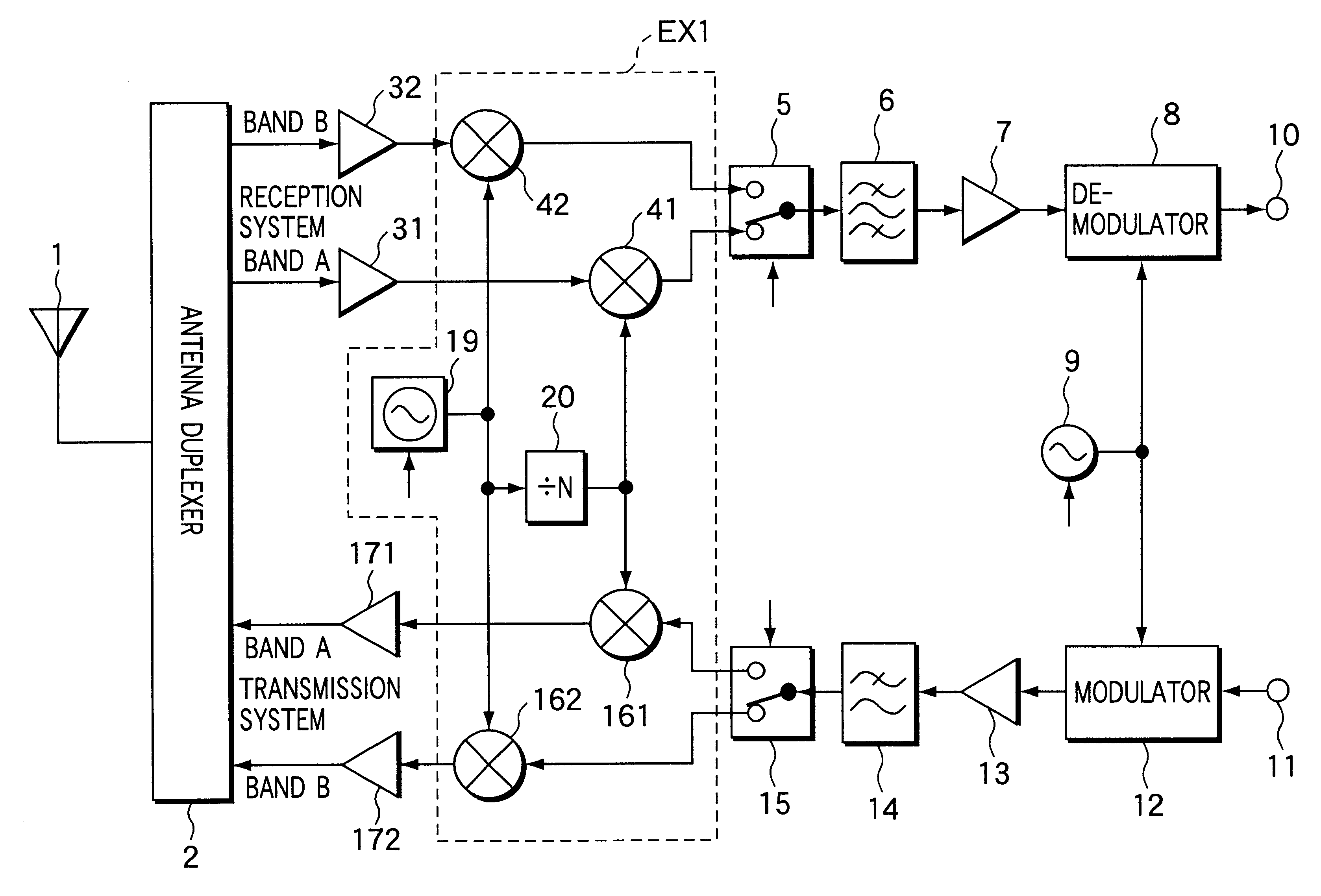
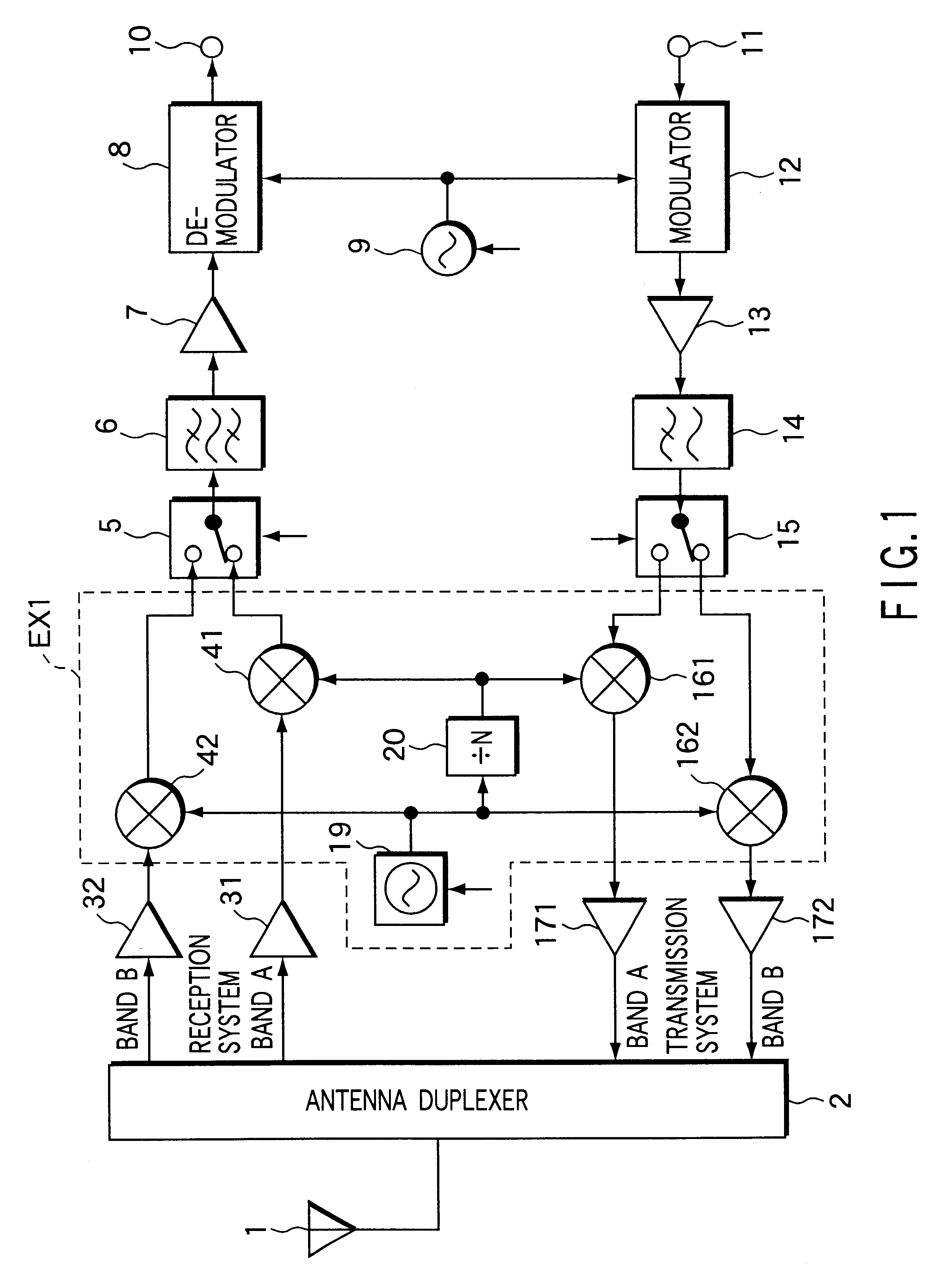
Referring now to FIG. 1, there is shown an arrangement of radiocommunication apparatus according to an embodiment of the present invention. In this figure, like reference numerals are used to denote corresponding components to those in FIG. 1.

An antenna 1 is one that, as shown in FIG. 3, is capable of transmitting and receiving signals in frequency bands (bands A and B) which are allocated to two radiocommunication systems, respectively.

Signals in the two frequency bands received by the antenna 1 is divided in an antenna duplexer 2. The received signal in the band A is applied to a low-noise amplifier 31, while the received signal in the band B is applied to a low-noise amplifier 32.

The received signal in the band A is amplified by the low-noise amplifier 31, while the signal in the band B is amplified by the low-noise amplifier 32. The amplified received signals in the bands A and B are both applied to a frequency converter EX1. The frequency converter EX1 comprises first and secon...


PUM


Abstract

In radiocommunication apparatus, two downconverters (41, 42) for use in reception system each heterodyne their respective received RF signal to an intermediate frequency. One of the downconverters employs a local signal generated by a synthesizer (19), and the other employs a signal obtained by dividing the frequency of the local signal by a factor of N. Two upconverters (161, 162) for use in transmission system each convert their respective input transmit signal to a transmit RF signal. One of the upconverters employs a local signal generated by the synthesizer (19) and the other employs a signal obtained by dividing the frequency of the local signal by a factor of N.

Description

The present invention relates to radiocommunication apparatus which makes communication selectively using one of frequency bands respectively allocated to two communication systems such as GSM (Global system for Mobile Telecommunications) 900 and DCS (Digital Cellular System) 1800.As is well known, there is radiocommunication apparatus that is capable of making communication selectively using one of frequency bands respectively allocated to two communication systems. FIG. 7 shows a basic arrangement of this type of radiocommunication apparatus. The conventional radiocommunication apparatus will be described below with reference to FIG. 7.An antenna 1 is one that is capable of transmitting and receiving signals in frequency bands A and B (hereinafter referred simply as to bands A and B) which are allocated to two radiocommunication systems, respectively.Signals received by the antenna 1 is divided in an antenna duplexer 2. The received signal in the band A is applied to a low-noise a...

Claims


Application Information

Patent Timeline
Patent Type & Authority Patents(United States)
IPC IPC(8): H03D7/16H03D7/00H04B1/40H04B1/04H04B1/26H04B1/3822
CPCH03D7/163H04B1/406H04B1/006H04B1/005
Inventor MIZUMOTO, TORUSHIMIZU, HIROAKITOKUNAGA, TATSUYATORII, KENICHI
Owner KK TOSHIBA
Why Eureka
Try Eureka