Airflow guide stator vane for axial flow fan and shrouded axial flow fan assembly having such airflow guide stator vanes

Inactive Publication Date: 2002-06-04
HANON SYST
View PDF5 Cites 72 Cited by
  • Summary
  • Abstract
  • Description
  • Claims
  • Application Information

AI Technical Summary

Problems solved by technology

Since such a pusher-type axial flow fan assembly has a low blowing efficiency, it is used only when the space, formed behind the heat exchanger in an engine room, is significantly limited.
However, since the conventional axial flow fan assemblies including the shrouded axial flow fan assembly described in FIG. 1, the fan and housing described in U.S. Pat. No. 4,548,548 and the fan stator as

Method used


Image

  • Airflow guide stator vane for axial flow fan and shrouded axial flow fan assembly having such airflow guide stator vanes
  • Airflow guide stator vane for axial flow fan and shrouded axial flow fan assembly having such airflow guide stator vanes
  • Airflow guide stator vane for axial flow fan and shrouded axial flow fan assembly having such airflow guide stator vanes

Examples


embodiment 1

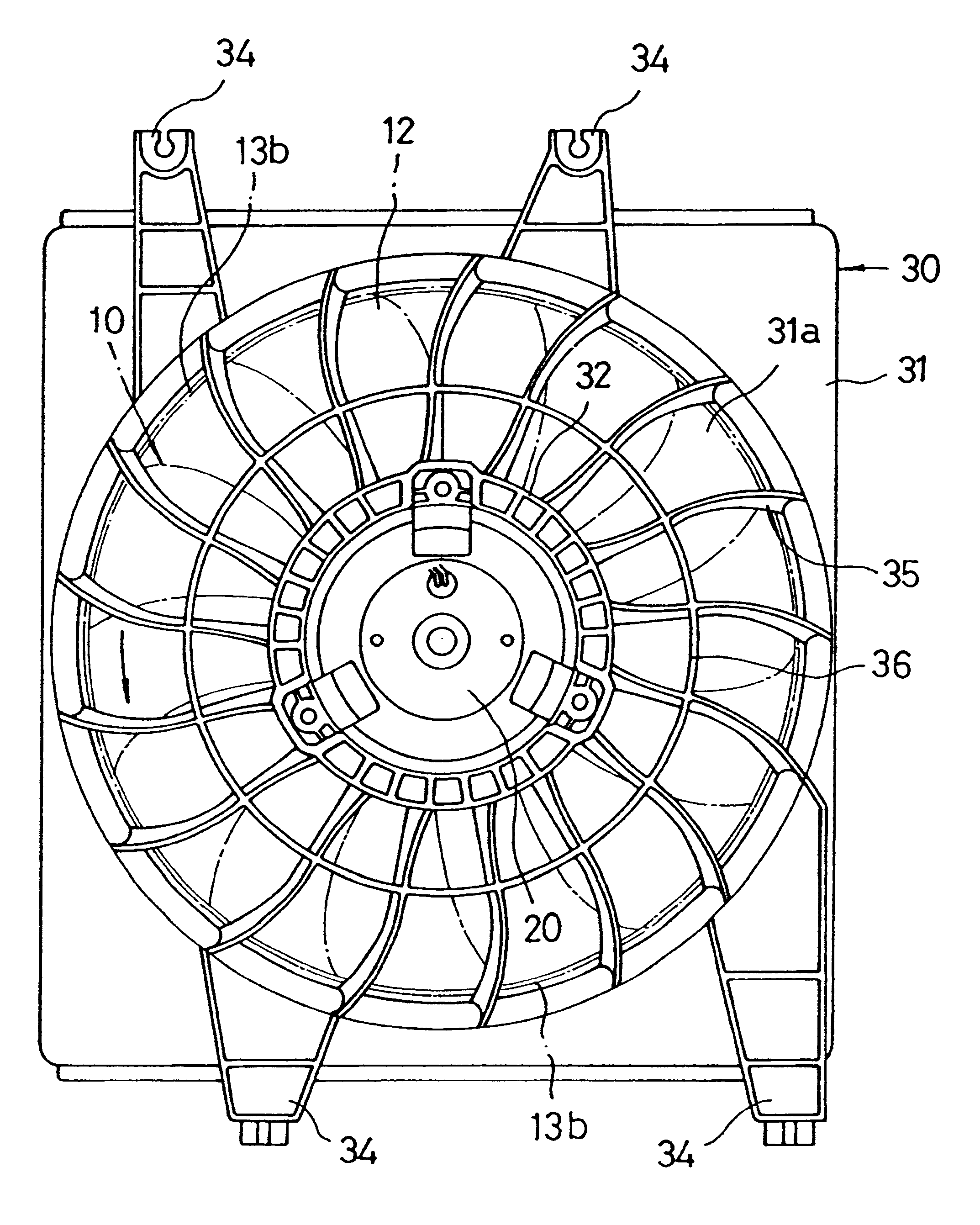
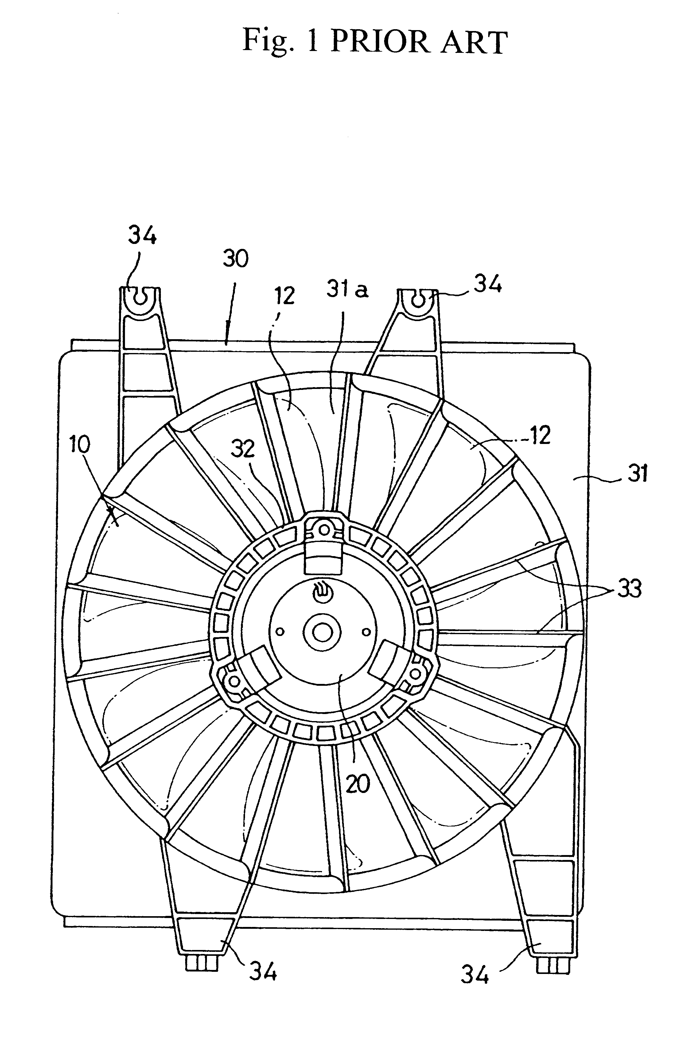
As shown in FIGS. 3 and 4, an axial flow fan assembly comprises an axial flow fan 10 and a shroud 30.

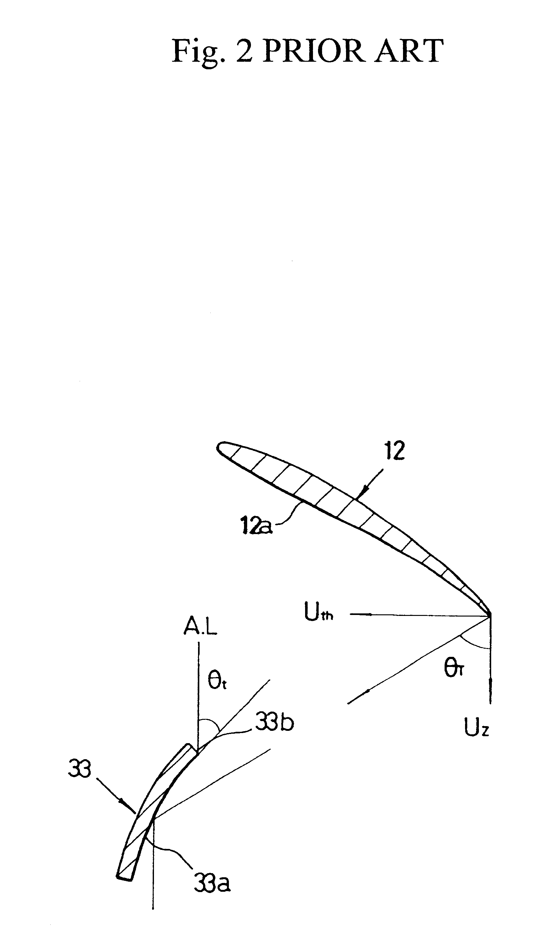
In this embodiment, the axial flow fan 10 consists of a circular central hub 11 positioned at its center portion and a plurality of blades 12 radially arranged along the 30 circumference of the hub 11. The shroud 10 consists of a motor support 32 holding the axial flow fan 10 and a motor 20 for driving the axial flow fan 10, a plurality of airflow guide stator vanes 33 radially arranged along the circumference of the motor support 32, and a rectangular housing 31 surrounding the peripheral ends of the axial flow fan 10 and the stator vanes 33.

In the axial flow fan 10 of this embodiment, the central hub 11 is connected with the driving shaft of a motor 20. The blades 12 are radially arranged along the circumference of the hub 11, are rotated together with the hub 11 and generate airflow. Incidentally, the axial flow fan 10 may be provided with an outer band 13 to which the peripheral...

embodiment 2

FIG. 14 illustrates a shrouded axial flow fan assembly according to The shrouded axial flow fan assembly is provided with a detachable stator 40. The detachable stator vanes 40 and the other parts are assembled together into the shrouded axial flow fan assembly illustrated in FIGS. 14 and 15.

The shrouded axial flow fan of this embodiment is like that of the previous embodiment except that the shrouded axial flow fan assembly is provided with the detachable stator 40 as a separate part. That is, as shown in FIG. 16, the detachable stator 40 is a distinct part separated from a shroud 40 with the radially inner ends of the vanes 41 of the stator 40 being fixed to the center ring 42 of the stator 40 and the radially outer ends of the vanes 41 of the stator 40 being fixed to the outer frame 43 of the stator 40. The stator 40 is detachably fitted into a mount groove 31c that is formed in the housing 31 of a shroud 30. In the meantime, each of the vanes 41 of the stator 40 is curved so th...


PUM


Abstract

An airflow guide stator vane for an axial flow fan and a shrouded axial flow fan assembly having such stator vanes are disclosed. The airflow guide stator vane has a leading edge line, a trailing edge line, and an airflow guide surface extending from the leading edge line to the trailing edge line. The stator vane is radially positioned in an axial flow fan and is curved so that its leading edge line is perpendicular to oblique velocity components of an airflow each of which is a sum vector of a rotation-directional velocity component and a radius-directional component of an air particle of the airflow. The axial flow fan assembly comprises an axial flow fan and a shroud. The axial flow fan consists of a circular central hub connected with a driving shaft of a motor and a plurality of blades radially arranged along the circumference of the hub. The shroud consists of a housing surrounding the peripheral ends of said axial flow fan and forming an airflow passage, a motor support being positioned at its center portion and holding a motor for driving said axial flow fan, and the above-described stator vanes.

Description

1. Field of the InventionThe present invention relates, in general, to axial flow fans and, more particularly, to an airflow guide stator vane for an axial flow fan capable of guiding air having dimensional velocity components along the axial direction, and a shrouded axial flow fan assembly having such airflow guide stator vanes.2. Description of the Prior ArtAs well known to those skilled in the art, an axial flow fan is a kind of fluid machinery and serves to blow air in the axial direction by the rotation of a plurality of radially arranged blades. Generally, the axial flow fan is used in conjunction with a shroud, the shroud surrounding the blades and guiding air toward the axial direction.Such a shrouded axial flow fan assembly is used to ventilate a room and promote the heat radiation of an air-cooled heat exchanger, such as a radiator or a condenser of an automobile. The shrouded axial flow fan assembly may promote heat radiation by blowing air to or drawing air from the hea...

Claims


Application Information

Patent Timeline
IPC IPC(8): F04D29/54F04D29/40F04D29/44
CPCF04D29/544F04D29/44
Inventor CHO, KYUNG SEOKMIN, OK RYUL
Owner HANON SYST
Why Eureka
Try Eureka