Active confocal image acquisition apparatus and method of three-dimensional measurement using same

Inactive Publication Date: 2002-06-04
TAKAOKA ELECTRIC MFG
View PDF2 Cites 37 Cited by
  • Summary
  • Abstract
  • Description
  • Claims
  • Application Information

AI Technical Summary

Benefits of technology

will hereinafter become more readily a

Problems solved by technology

However, a primitive method of three-dimensional measurement whereby the object is moved in the X and Y directions in a systematic pattern with respect to the objective lens at each height of stepwise scanning in the Z direction takes a very long time.
However, there is a problem with three-dimensional measurement by these confocal image acquisition systems; if there are high- and low-reflectance regions or regular- and scatter-reflection regions together in the measuring field, it is difficult to measure both regions at the same time.
Therefore, the above described problem can inevitably occur.
Coexistence of area with a very large difference between their intensities of reflection in a measuring field can cause not only the problem of the dynamic range but also another problem.
However, if there is a great difference between the reflectances of the points of the surface illuminated by adja

Method used


Image

  • Active confocal image acquisition apparatus and method of three-dimensional measurement using same
  • Active confocal image acquisition apparatus and method of three-dimensional measurement using same
  • Active confocal image acquisition apparatus and method of three-dimensional measurement using same

Examples


first embodiment

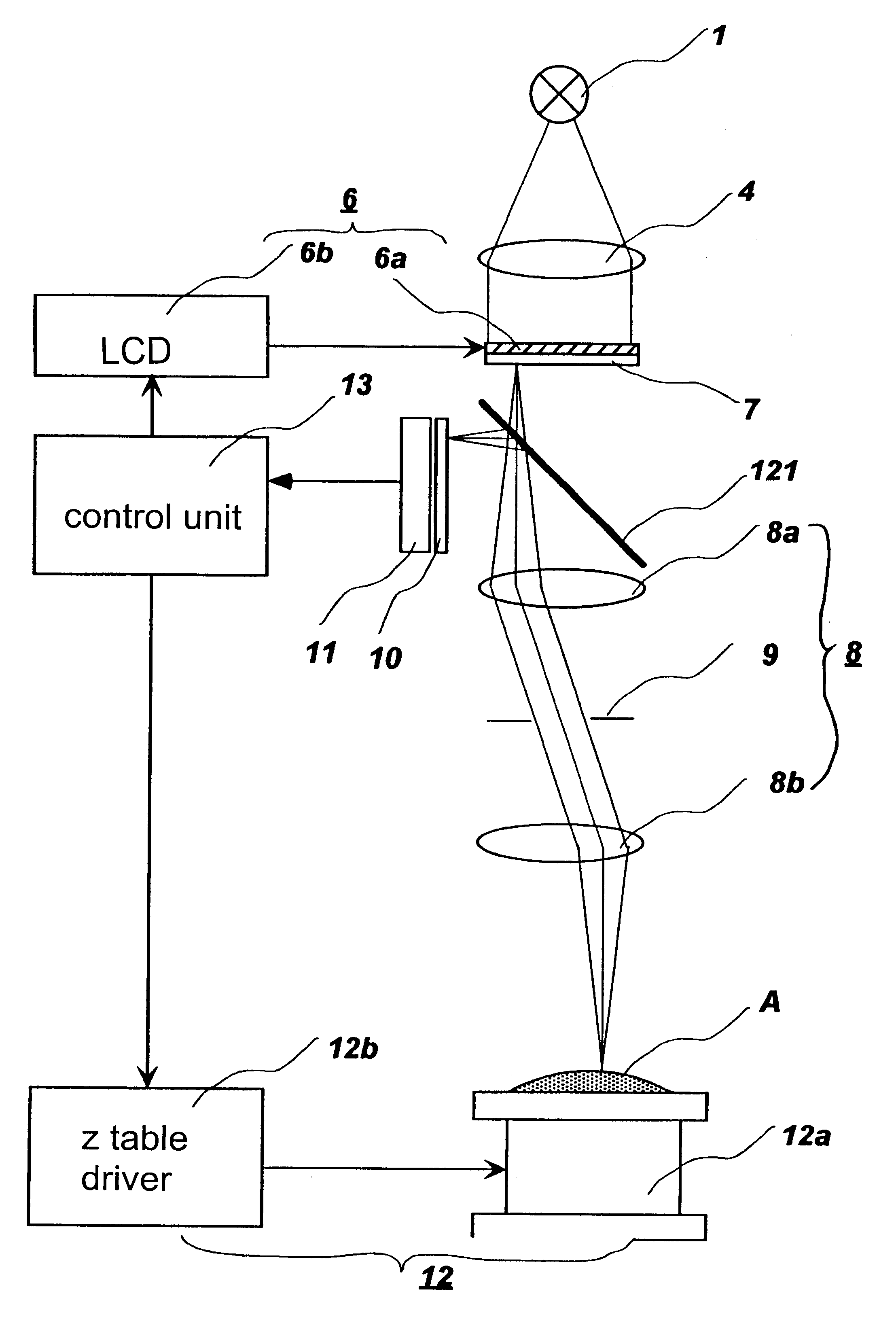
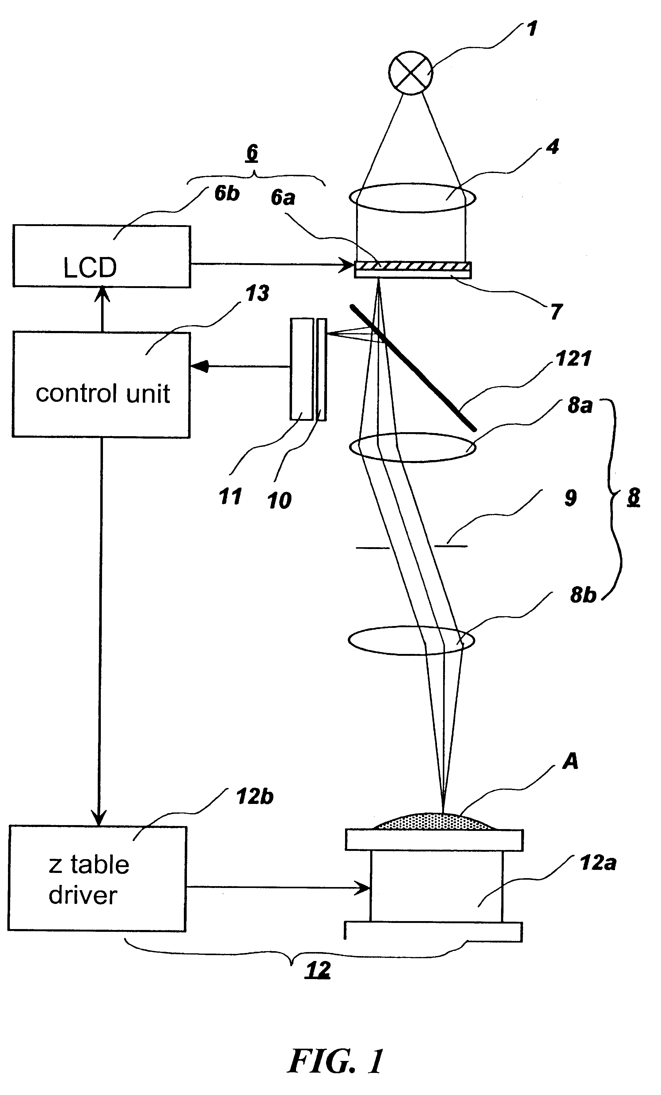
Preferred embodiments of the present invention are described below with reference to the drawings. FIG. 1 shows the present invention. The basic configuration of the active confocal optical system of this embodiment is the same as that of prior art B. Only the difference is explained below to avoid repetition. The difference is that the light intensity control means 6 is disposed above the pinhole array 7 as shown in FIG. 1. The light intensity control means 6 consists of the LCD (Liquid crystal panel) 6a and the LCD driver 6b. The LCD 6a is aligned with the pinhole array 7 so that each pixel is positioned right above the corresponding pinhole of the pinhole array 7. The LCD driver 6b may be built in the LCD 6a or separately housed.

In the system shown in FIG. 1, the processing and control unit 13 captures confocal images through the detector array 11, moving the object with respect to the optical system by means of the Z scanning means 12 consisting of the Z table 12a and the Z tabl...

second embodiment

the present invention is shown in FIG. 4. This embodiment is the same as the first embodiment except that the LCD 6a is attached to the detecting pinhole array 10. Although the first embodiment is the better for reducing stray light, fundamentally the same effect can be obtained by both embodiments.

third embodiment

the present invention is shown in FIG. 5. This embodiment has the configuration of prior art C with the light intensity control means 6 added. Since it has only one pinhole array serving both as the illuminating and detecting pinhole arrays, attaching a light intensity control means to the pinhole array is equivalent to attaching a light intensity control means to both the illuminating and detecting pinhole arrays of the first and second embodiments. Therefore, the intensity of light that reaches each element of the detector array 11 is in proportion to the square of the transmittance of the corresponding pixel of the light intensity control means 6.


PUM


Abstract

An active confocal image acquisition apparatus includes a confocal image acquisition system and a liquid crystal panel. The liquid crystal panel is disposed in the confocal image acquisition system so that its elements are aligned with elements of the detector. The light transmittance of elements of the liquid crystal panel is adjusted so as to make the intensities of reflection of all pixels (the values attained when the parts reflecting light are at or near the focused position) as close to a predetermined level as possible. By this configuration and method of using it, the active confocal image acquisition apparatus can perform accurate measurement if there are high-reflectance and low-reflectance parts together in the measuring field.

Description

1. Field of the InventionThe present invention relates to an optical apparatus for capturing confocal images and a method of three-dimensional measurement using the apparatus.2. Discussion of the BackgroundBy utilizing a confocal optical system, the position (hereinafter referred to as the height) of the object measured in the direction of the optical axis (hereinafter referred to as the z-axis direction) can be measured accurately. Before description of the prior art, the principle of measurement of the height by a confocal optical system is explained. A basic configuration of the confocal optical system is shown in FIG. 10. Illumination emitted from the point light source 101 passes through the half-mirror 102 and is refracted by the objective lens 103 to converge on the object. The light that is reflected by the object and enters the objective lens 103 again is converged by the objective lens 103 and then diverted by the half-mirror 102 toward the pinhole 104 disposed at the same...

Claims


Application Information

Patent Timeline
IPC IPC(8): G02B21/00G01B11/00G01B11/24G02F1/13
CPCG02B21/0068G02B21/004
Inventor ISHIHARA, MITSUHIRO
Owner TAKAOKA ELECTRIC MFG
Why Eureka
Try Eureka