Omni-directional ultrasonic transducer apparatus and staking method

a transducer and ultrasonic technology, applied in the direction of mechanical vibration separation, piezoelectric/electrostrictive/magnetostrictive devices, piezoelectric/electrostriction/magnetostriction machines, etc., can solve the problems of uncontrollable resonance frequency and a reduced vibration of the pvdf film

Inactive Publication Date: 2002-06-04
MEASUREMENT SPEC
View PDF7 Cites 61 Cited by
  • Summary
  • Abstract
  • Description
  • Claims
  • Application Information

AI Technical Summary

Problems solved by technology

However, in the known application of a film to a spool as described, a problem has been discovered by the inventors of the instant application.
Specifically, it has been discovered that with the "gap-free" wrapping of semi-cylindrical or cylindrical film attempted in the known art, there are problems of uncontrollable resonance frequency and a reduced vibration of the PVDF film.
In addition, it has been discovered by the instant inventors that the bonding of the film to a film support, such as a cylinder, contributes to the problems of uncontrollable resonance frequency and reduced vibration of the PVDF film.
Since a thickness of the back air space is not controlled in the known art, nor recognized that it could or should be controlled, the resonance frequency also can not be controlled.

Method used


Image

  • Omni-directional ultrasonic transducer apparatus and staking method
  • Omni-directional ultrasonic transducer apparatus and staking method
  • Omni-directional ultrasonic transducer apparatus and staking method

Examples


first embodiment

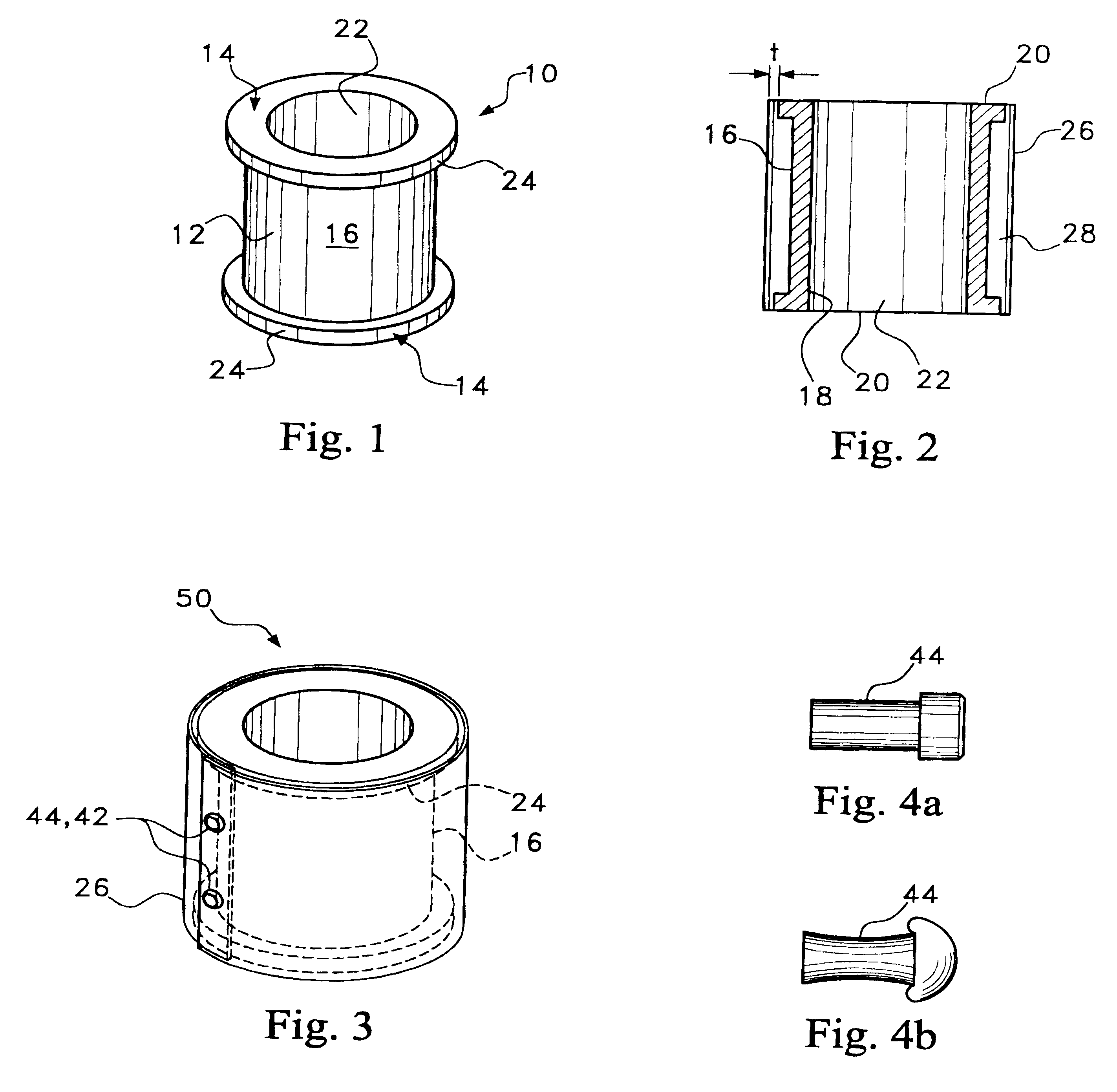
FIG. 3 is a perspective view of the combined spool and film showing joining edges of the film;

FIG. 4A is a side view of a thermally deformable nail used in the option of FIG. 3 prior to thermal deformation;

FIG. 4B is a side view of the thermally deformable nail used in the option of FIG. 3 subsequent to thermal deformation;

second embodiment

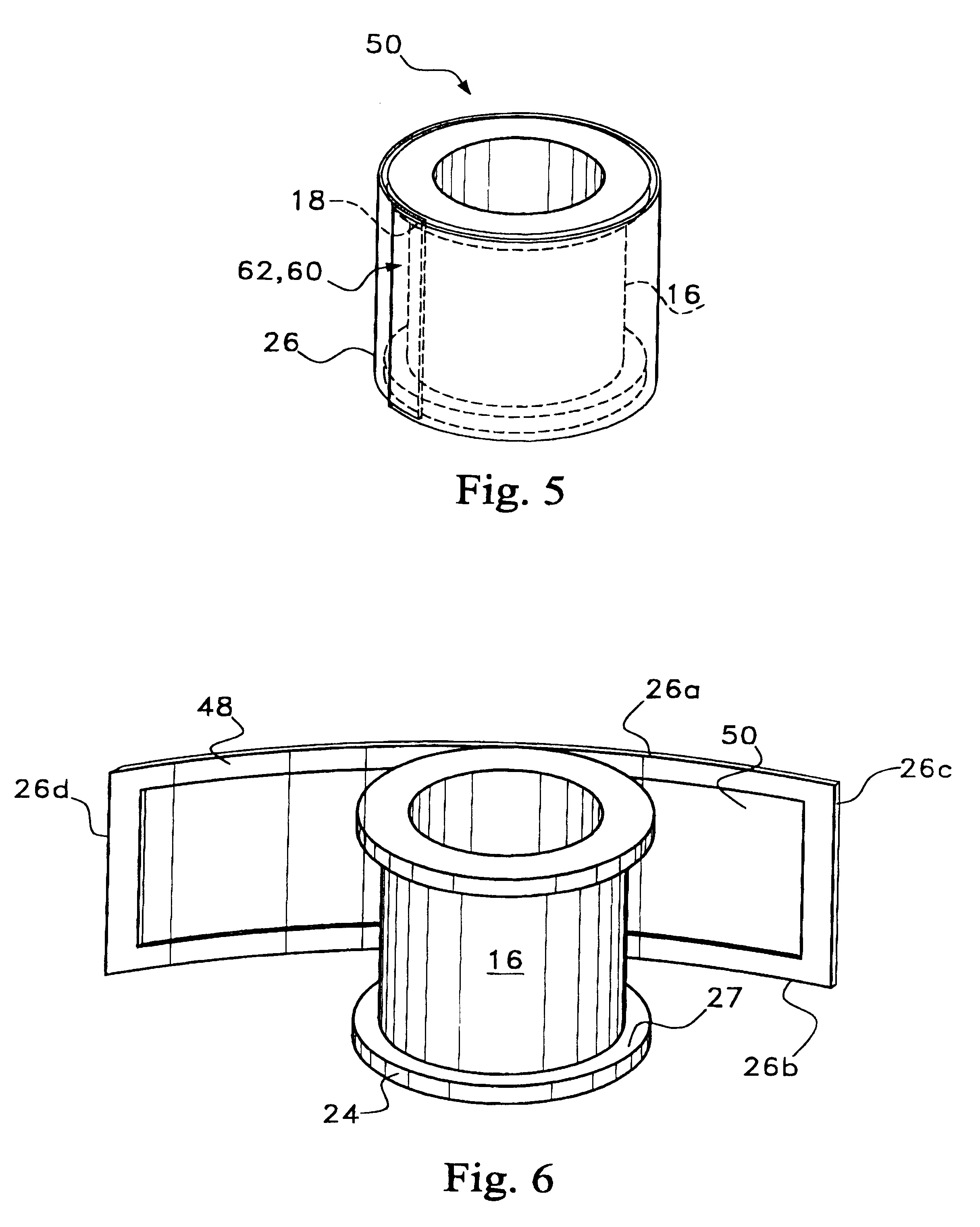
FIG. 5 is a perspective view of the combined spool and film showing joining edges of the film;

third embodiment

FIG. 6 is a perspective view of the spool with an unwrapped film according to the present invention;

FIG. 7 is a perspective view of a conventional PVDF film;

FIG. 8 is a perspective view of the conventional PVDF film of FIG. 5 applied to a conventional spool;

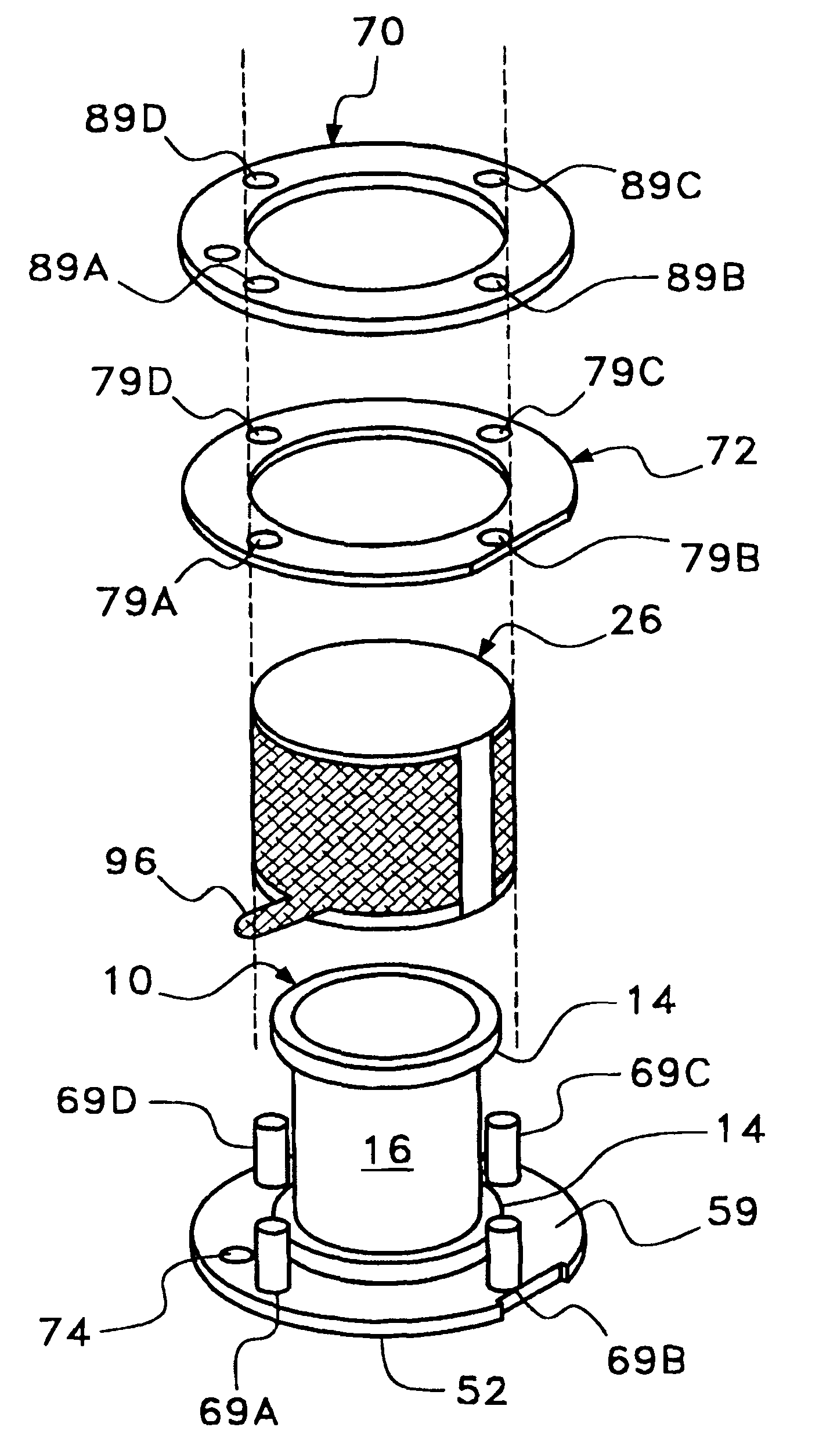
FIG. 9A is a schematic representation of a method for ultrasonically staking the PVDF film disposed on the spool to a printed circuit board according to an aspect of the invention.

FIG. 9B is a schematic representation of the assembled ultrasonically staked ultrasonic transducer according to the method illustrated in FIG. 9A.

FIG. 10A is a schematic representation of an alternative method for ultrasonically staking the PVDF film disposed on the spool directly to a printed circuit board according to another aspect of the invention.

FIG. 10B is a schematic representation of the assembled ultrasonically staked ultrasonic transducer according to the method illustrated in FIG. 10A.

While the present invention may have many applications, a...


PUM


Abstract

A transducer apparatus is disclosed having a spool member with a body portion and first and second elevated regions formed on the body portion. A PVDF film surrounds the spool member, the film including an inner surface facing the spool member and an outer surface opposite the inner surface. The film as surrounding the spool member has a predetermined frequency of resonance. Lateral ends of the film are secured together by a securing material. The securing material is such that the secured ends of the film will have substantially the same resonance frequency as a remainder of the film. The film includes a non-electrode area at a perimeter of the inner surface and an electrode material formed on a remainder of the inner surface. Upon securing the lateral edges of the film together, the securement is at overlapping non-electrode lateral edges of the film. The securing material may be any one of an adhesive in combination with screws or thermally deformable nails, adhesive alone, tape, or ultrasonic welding.

Description

The present invention relates to the field of transducers. More particularly, the present invention relates to an omni-directional ultrasonic transducer apparatus.DESCRIPTION OF RELATED ARTIn the environment of transducers, it is known that an ultrasonic transducer may be formed with either a linear or curved film incorporated therein. In the event that a curved film is used, the ends of the curved film are butted up against each other with no apparent connection between the butted ends. Each of the types of film is described in the following.Referring first to FIG. 7, a linear polymer piezoelectric film 70 is shown. When an AC voltage is applied to electrodes 72 on surfaces of the film 70, the film length in the molecular chain direction shrinks or expands. In other words, the PVDF film (the polymer piezoelectric material) is stretched during the process and molecular chains are aligned in parallel. This is due to excitation in the linear direction.Alternatively, a cylindrical piez...

Claims


Application Information

Patent Timeline
Patent Type & Authority Patents(United States)
IPC IPC(8): B06B1/06H01L41/00H01L41/053
CPCB06B1/0655B06B1/0688Y10S310/80
Inventor TODA, MINORUPARK, KYUNG-TAEZAKS, SUSAN HUANGSWAN, JEFFREY D.
Owner MEASUREMENT SPEC
Why Eureka
Try Eureka