Cathode-ray tube device comprising a deflection yoke with a non-circular core having specified dimensional relationships

a cathode-ray tube and deflection yoke technology, which is applied in the direction of cathode ray tubes/electron beam tubes, electrical devices, electric discharge tubes, etc., can solve the problems of poor safety, difficult to reduce the deflection power and leakage magnetic field, and the failure of the display to fail, etc., to achieve high brightness, high definition, and sufficient bulb strength

Inactive Publication Date: 2002-06-11
KK TOSHIBA
View PDF16 Cites 10 Cited by
  • Summary
  • Abstract
  • Description
  • Claims
  • Application Information

AI Technical Summary

Benefits of technology

The present invention has been developed to solve the above-mentioned problem and the object thereof is to provide a cathode ray tube apparatus in which a sufficient bulb strength can be secured even in the case where the yoke portion of the vacuum envelope is substantially pyramidal, and in which the requirement for high brightness and high definition can be met even after the deflection power and the leakage magnetic field are reduced.

Problems solved by technology

Such an electron beam fails to impinge on the phosphor screen and causes a display failure.
In the cathode ray tube apparatus having this construction, it is difficult to reduce the deflection power and the leakage magnetic field by reducing the outer diameters of the neck portion and the yoke portion.
Thus the safety is adversely affected.
In the flat display unit with an outer surface having a radius of curvature at least twice the effective diagonal length of the phosphor screen (the faceplate is completely flat when the radius of curvature is infinitely large), however, the environmental pressure resistance of the faceplate is low.
Additionally, the yoke portion, if pyramidal, decreases also in the environmental pressure resistance, thereby making it difficult to secure a mechanical strength required of the vacuum envelope as a whole for safety.
The two requirements described above, that is, a rectangular section of the yoke portion in order to sufficiently reduce the deflection power and the leakage magnetic field on the one hand and a sufficient bulb strength even with a rectangular section of the yoke portion on the other, cannot be met at the same time by the conventional cathode ray tube apparatus.
It is especially difficult for the cathode ray tube apparatus with a flat display unit to reduce the deflection power and the leakage magnetic field and a sufficient bulb strength at the same time.

Method used


Image

  • Cathode-ray tube device comprising a deflection yoke with a non-circular core having specified dimensional relationships
  • Cathode-ray tube device comprising a deflection yoke with a non-circular core having specified dimensional relationships
  • Cathode-ray tube device comprising a deflection yoke with a non-circular core having specified dimensional relationships

Examples


Embodiment Construction

A cathode ray tube apparatus according to an embodiment of the present invention will be described in detail below with reference to the drawings.

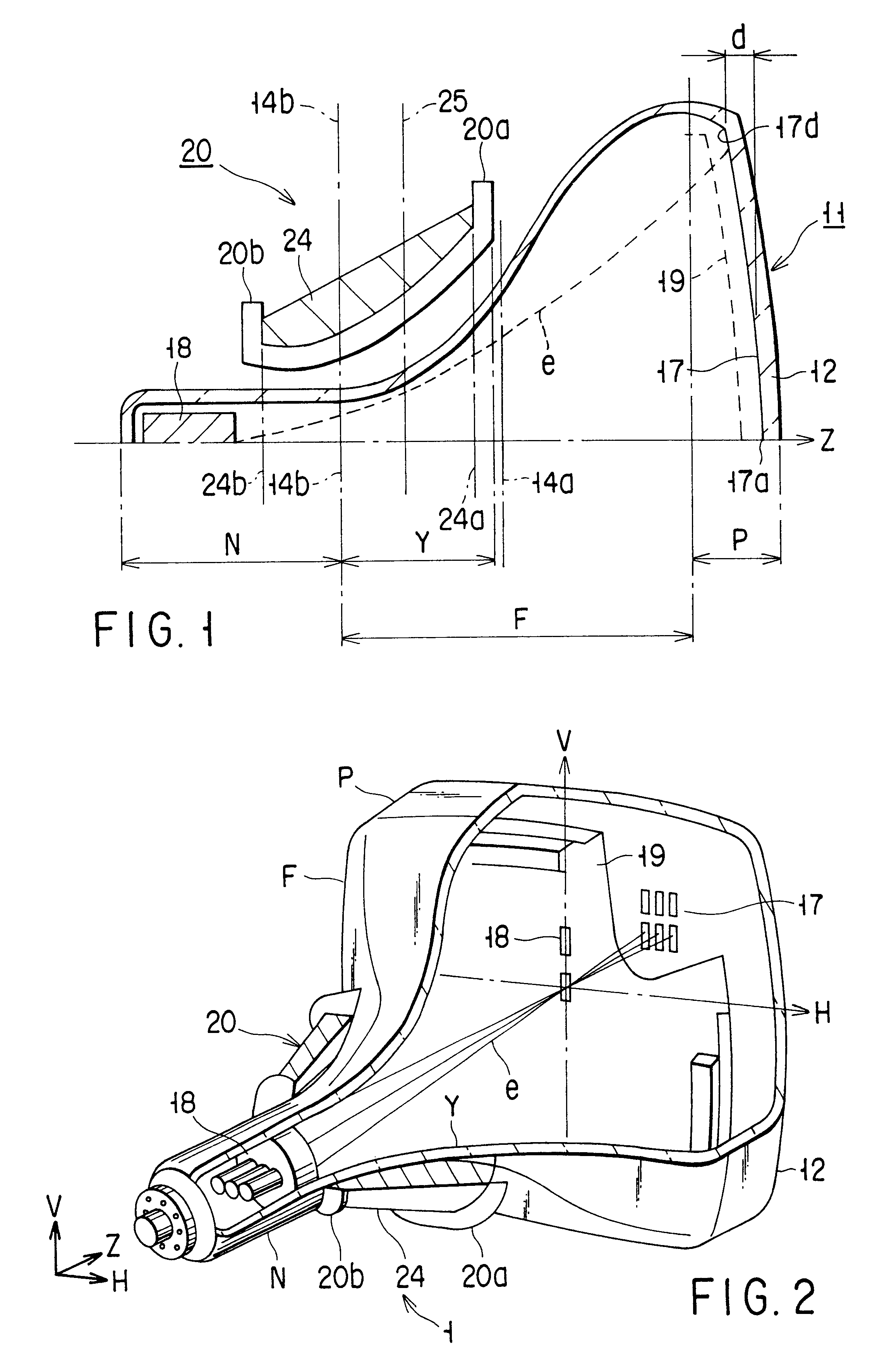
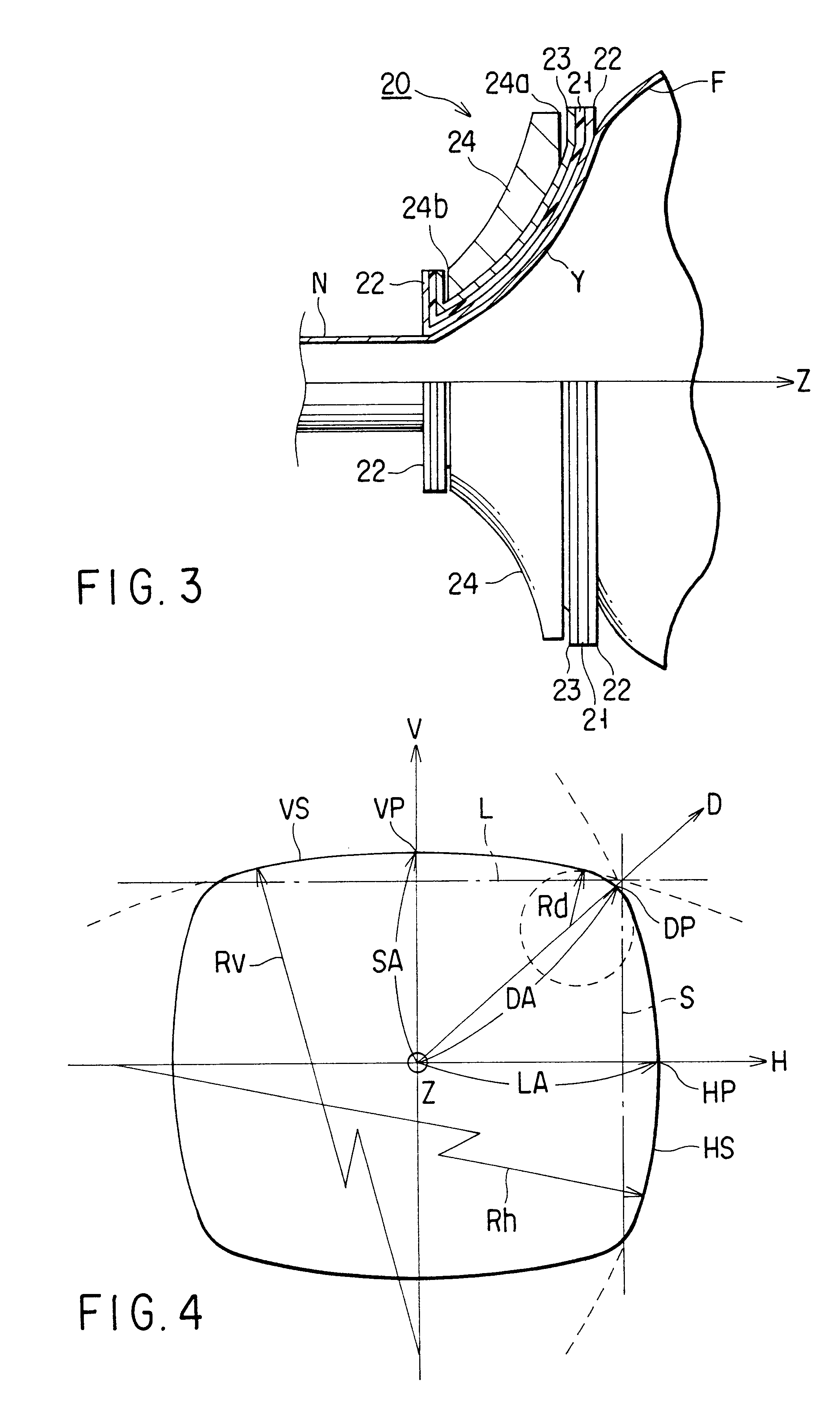
The invention provides a cathode ray tube apparatus comprising a vacuum envelope including a yoke portion having an optimum shape capable of reducing the deflection power and securing a sufficient bulb strength at the same time, and a deflection yoke of an optimum shape mounted on the yoke portion, when the yoke portion of the vacuum envelope is formed in a substantially pyramidal shape.

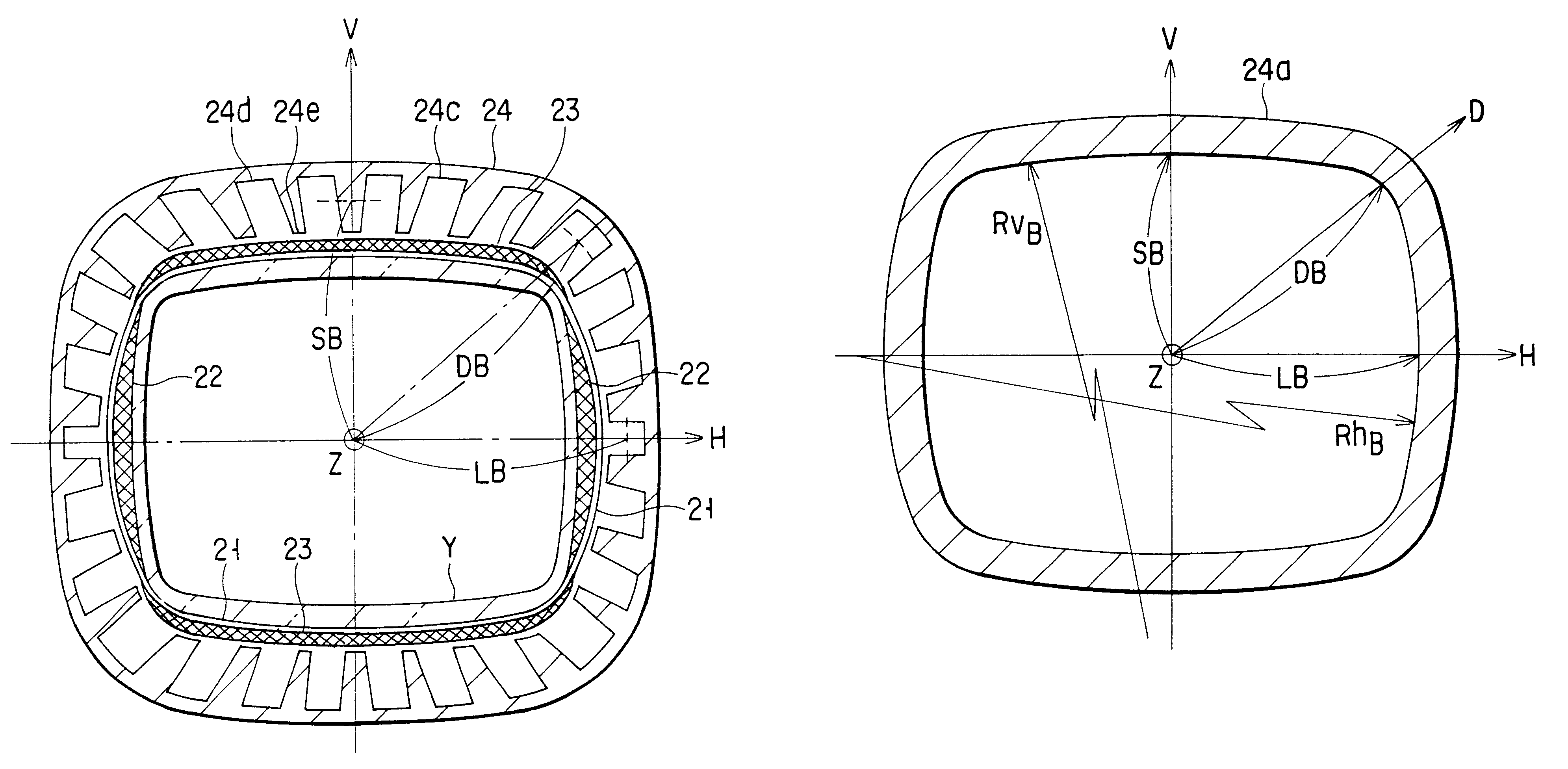
As shown in FIGS. 1 and 2, a cathode ray tube apparatus 1 comprises a vacuum envelope 11 made of glass and a deflection yoke 20 forming a deflection magnetic field for deflecting the electron beam. The vacuum envelope 11 includes a faceplate P having a substantially rectangular effective faceplate surface 12, a cylindrical neck portion N having a center axis coincident with the tube axis Z and a funnel portion F for coupling the faceplate P and the neck por...


PUM


Abstract

A section perpendicular to a tube axis, of a yoke portion having a deflection yoke mounted thereon is in the shape of a non-circle based on a rectangle. A section perpendicular to the tube axis, of a core portion of the deflection yoke has a shape holding the relationwhere M:N is an aspect ratio, SB is the inner diameter along the vertical axis, LB the inner diameter along the horizontal axis, and DB a maximum inner diameter.

Description

The present invention relates to a cathode ray tube apparatus, or more in particular, to a cathode ray tube apparatus comprising a deflection yoke capable of reducing the deflection power and the leakage magnetic field effectively and a vacuum envelope capable of securing a sufficient environmental pressure resistance.Generally, the cathode ray tube apparatus comprises a vacuum envelope made of glass and a deflection yoke forming a deflection magnetic field for deflecting electron beams. The vacuum envelope includes a rectangular faceplate, a cylindrical neck portion and a funnel portion for coupling the faceplate and the neck portion to each other. The deflection yoke is mounted over the portion extending from the neck portion to a yoke portion in the funnel portion.In the cathode ray tube apparatus having this construction, the deflection power supplied to the deflection yoke is the main power consumed in the apparatus. In recent years, in order to satisfy the requirement for high...

Claims


Application Information

Patent Timeline
Patent Type & Authority Patents(United States)
IPC IPC(8): H01J29/86H01J29/76
CPCH01J29/76H01J29/861H01J2229/8609H01J2229/7031
Inventor SONEDA, KOUICHISANO, YUUICHIYOKOTA, MASAHIRO
Owner KK TOSHIBA
Why Eureka
Try Eureka