Cab suspension system for terminal tractors

Inactive Publication Date: 2002-06-25
ENG ALLEN L
View PDF30 Cites 37 Cited by
  • Summary
  • Abstract
  • Description
  • Claims
  • Application Information

AI Technical Summary

Benefits of technology

Most terminal tractors are built with the rear axle mounted directly to the frame, referred to as a "hard tail" or "solid mount" which indicates the lack of a flexible rear suspension system on the chassis. These vehicles are known to create a hard ride with operator discomfort and maintenance cost increase to the vehicle. Rough terrain transfers shock loading to the cab causing the cabin to pitch, roll and backslap the driver throughout operation.
The industry standard four point mounting system has two front mounts allowing the cabs to tilt forward for maintenance. This prior art is shown in FIGS. 1 and 2 of the drawings. They are typically rubber bushings enclosed in steel sleeves with cap screws or pins inserted through the canters of the bushings to create the pivot point. Very limited movement is obtained by the rubber bushings and achieve less than 1/4 inch movement relative to the chassis. Virtually all pitch and roll movement of the chassis is transferred to the cab, causing the cabin to be thrown at every bump.
The rear mounts of the four point mounting system are rubber pads, cushions or rubber dock bumpers at both frame rails under the rear of the cab. They too are stiff and apply less than 1/4 inch deflection to cushion the ride. The cab bucks up and forward every time a bump is hit and the constant pitch, roll, bump and bucking of the cab leads to premature failure of all involved components. Electrical systems fail, connections vibrate loose, terminals crack and separate, lamps burn out or rupture, switches and resistors fail and motor life is shortened.
Major terminal tractor manufacturers have tried for years to develop a rear suspension system that would provide the flexibility to improve ride character and be adaptable for full and empty loading conditions, and durable for high cycle terminal applications. Air suspensions are expensive and difficult to maintain in terminal applications. Additionally, terminal tractor cabs do not adapt well to highway tractor applications because most, if not all, termin

Problems solved by technology

These vehicles are known to create a hard ride with operator discomfort and maintenance cost increase to the vehicle.
Rough terrain transfers shock loading to the cab causing the cabin to pitch, roll and backslap the driver throughout operation.
Very limited movement is obtained by the rubber bushings and achieve less than 1/4 inch movement relative to the chassis.
Virtually all pitch and roll movement of the

Method used


Image

  • Cab suspension system for terminal tractors
  • Cab suspension system for terminal tractors
  • Cab suspension system for terminal tractors

Examples


Embodiment Construction

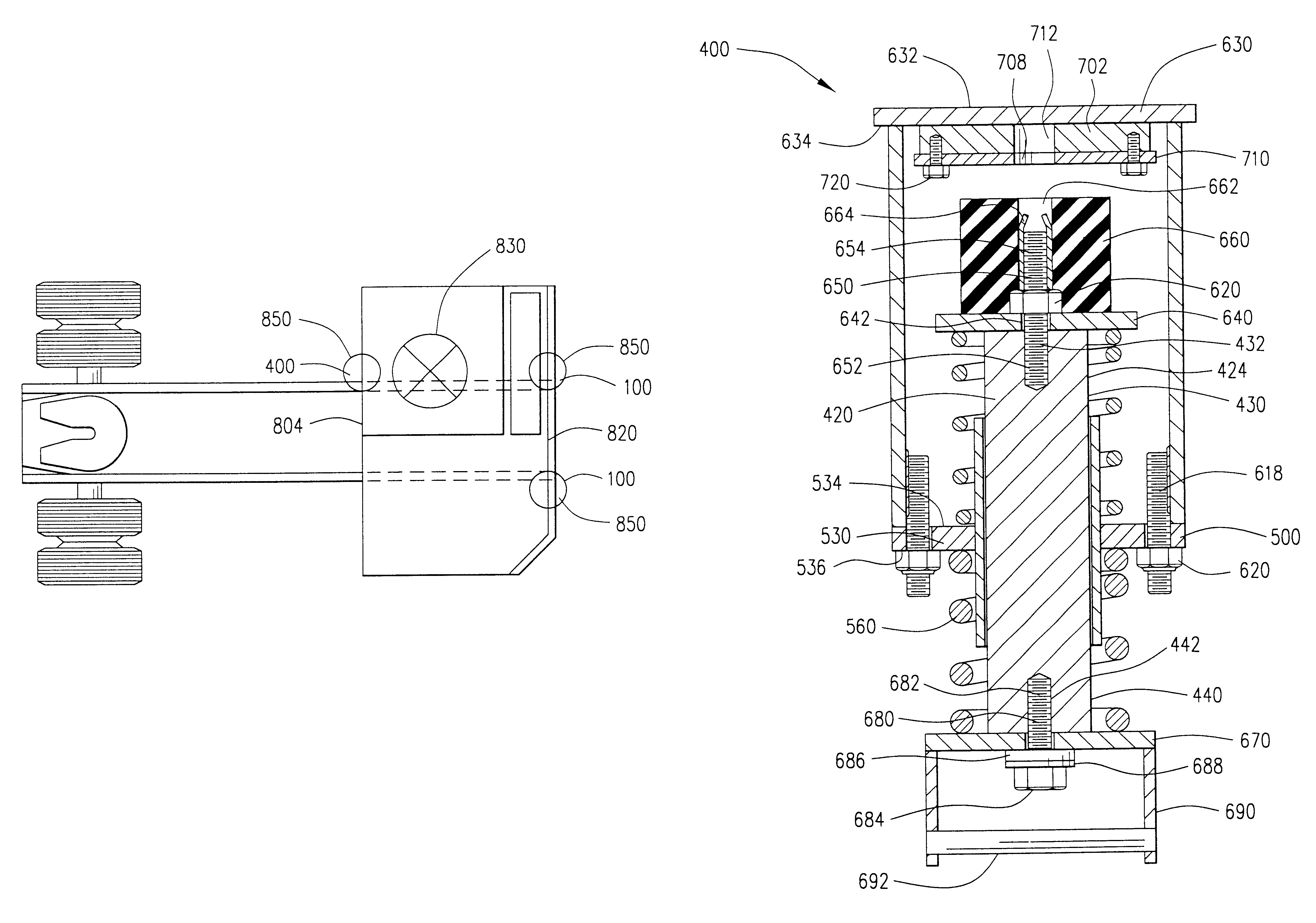
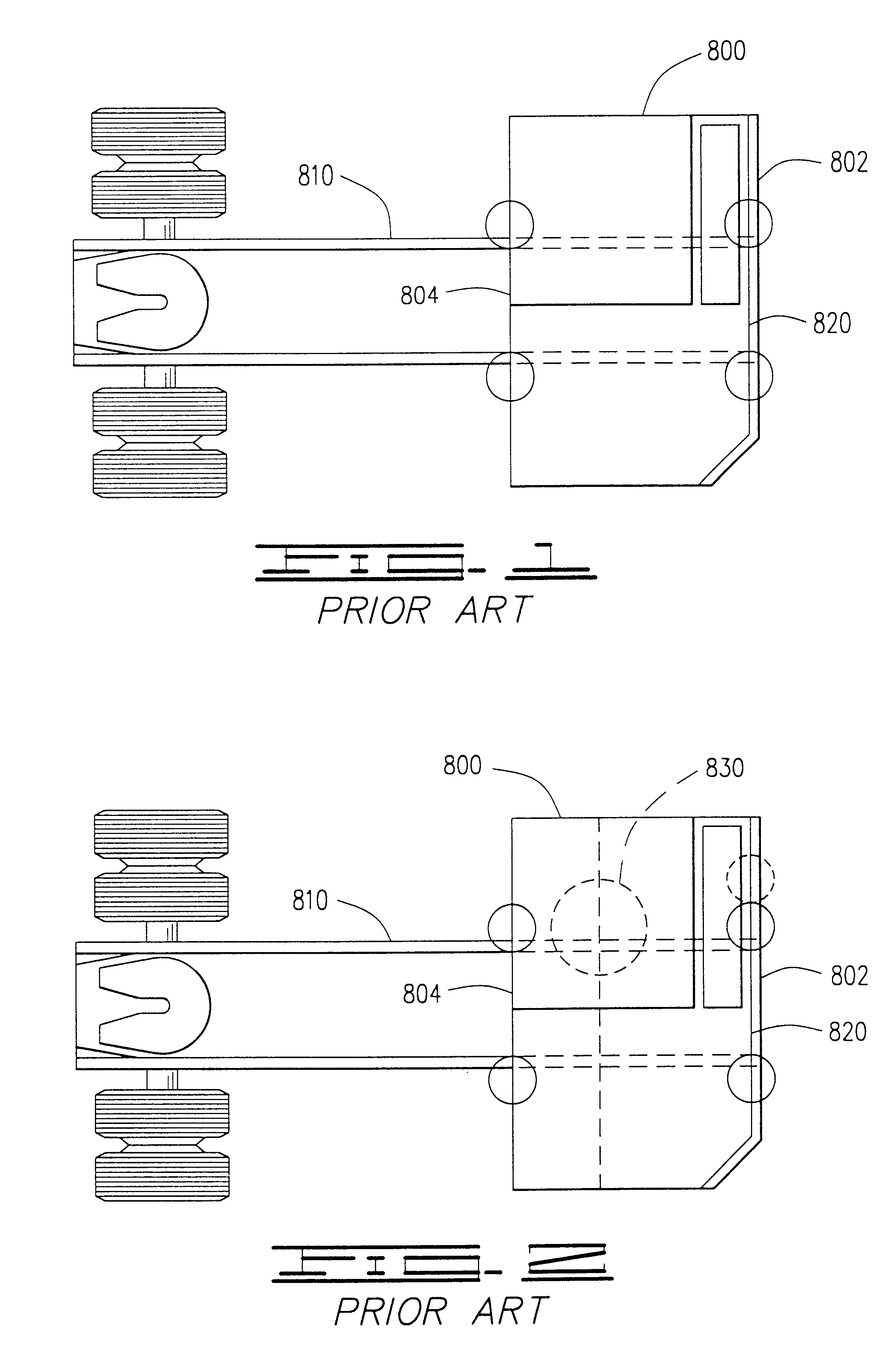
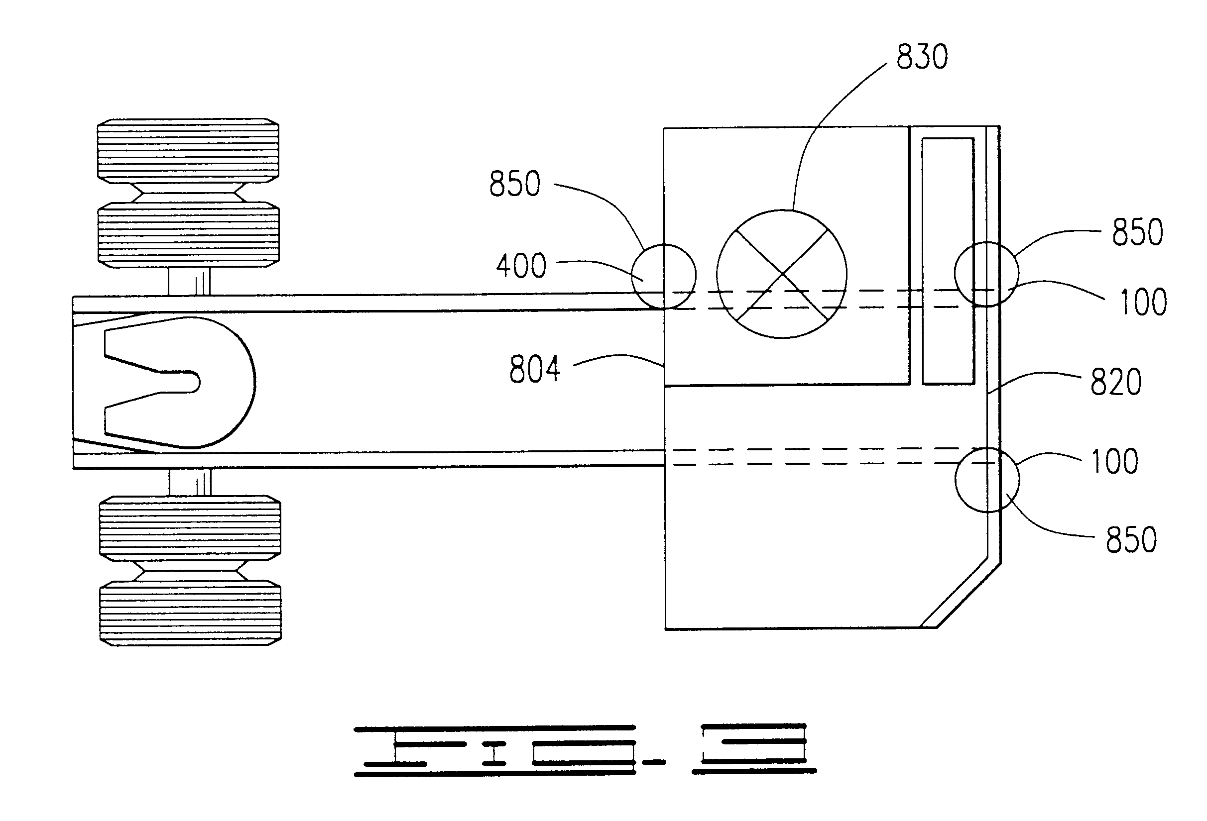
The invention, as shown in FIGS. 3-10 of the drawings, is a three point terminal tractor cab suspension system mounted to the frame of the terminal tractor comprising two front suspension assemblies 100 and one rear suspension assembly 400. Each front suspension assembly 100, as shown in FIGS. 5a, 5b of the drawings, includes a support shaft 120, a sleeve assembly 200, a carrier coil spring 260, a rebound coil spring 250, a pivot bushing assembly 370, an elastomeric spring 360 and a carrier housing assembly 300. These front suspension assemblies 100 are identical and are mounted to a front 802 of a terminal tractor 800 attaching a terminal tractor cab 820 to a terminal tractor frame 810 providing for pivot of the cab 820 for maintenance and repair access.

The rear suspension assembly 400, as shown in FIGS. 4a, 4b of the drawings, includes a support shaft 420, a sleeve assembly 500, a rebound coil spring 550, a carrier coil spring 560, an elastomeric spring 660, a latch catch assembly...


PUM


Abstract

The invention is a mechanical suspension system for cab-over tractors, specifically those used in terminal transport having two front cushion dual suspension components on the front pivot area of the cab to tractor frame connection and a single rear cushion dual suspension component on the rear of the tractor frame at the cab-over latch area, the three point dual suspension system providing a more stable suspension package than the four point and other single suspension systems.

Description

NoneI. BACKGROUND OF THE INVENTION1. Field of InventionThe invention is a mechanical suspension system for cab-over tractors, specifically those used in terminal transport of semi-trailers having two front cushion dual suspension components on the front pivot area of the cab to tractor frame connection and a single rear cushion dual suspension component on the rear of the tractor frame at the cab-over latch area, the three point dual suspension system providing a more stable suspension package than the four point and other currently available suspension systems.2. Description of Prior ArtThe following United States patents are disclosed herein and incorporated into this application for utility patent. All relate to suspension systems for heavy duty trucks or trains. A primary application for this current invention is for terminal tractors as disclosed in the brochure attached to the Form 1449, from Crane Carrier Company, or CCC.RTM..A suspension system for a vehicle cab including sp...

Claims


Application Information

Patent Timeline
IPC IPC(8): B60G25/00B62D33/06F16F3/10F16F3/00B60G99/00
CPCB60G99/006F16F3/10B62D33/0608B60G2202/12B60G2204/124B60G2300/024B60G2204/162
Inventor ENG, ALLEN L.
Owner ENG ALLEN L
Why Eureka
Try Eureka