

Bi-directional fluid ejection systems and methods
a fluid ejection and bi-directional technology, applied in printing and other directions, can solve problems such as suction of ink into
- Summary
- Abstract
- Description
- Claims
- Application Information
AI Technical Summary
Benefits of technology
Problems solved by technology
Method used
Image

Examples
Embodiment Construction
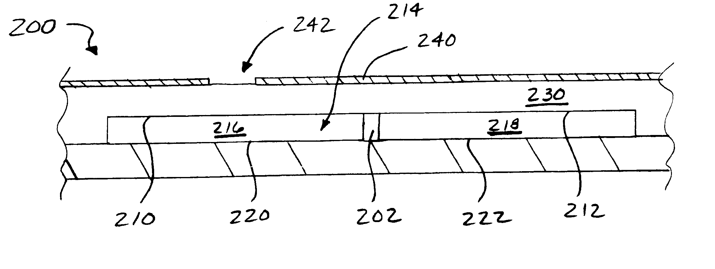
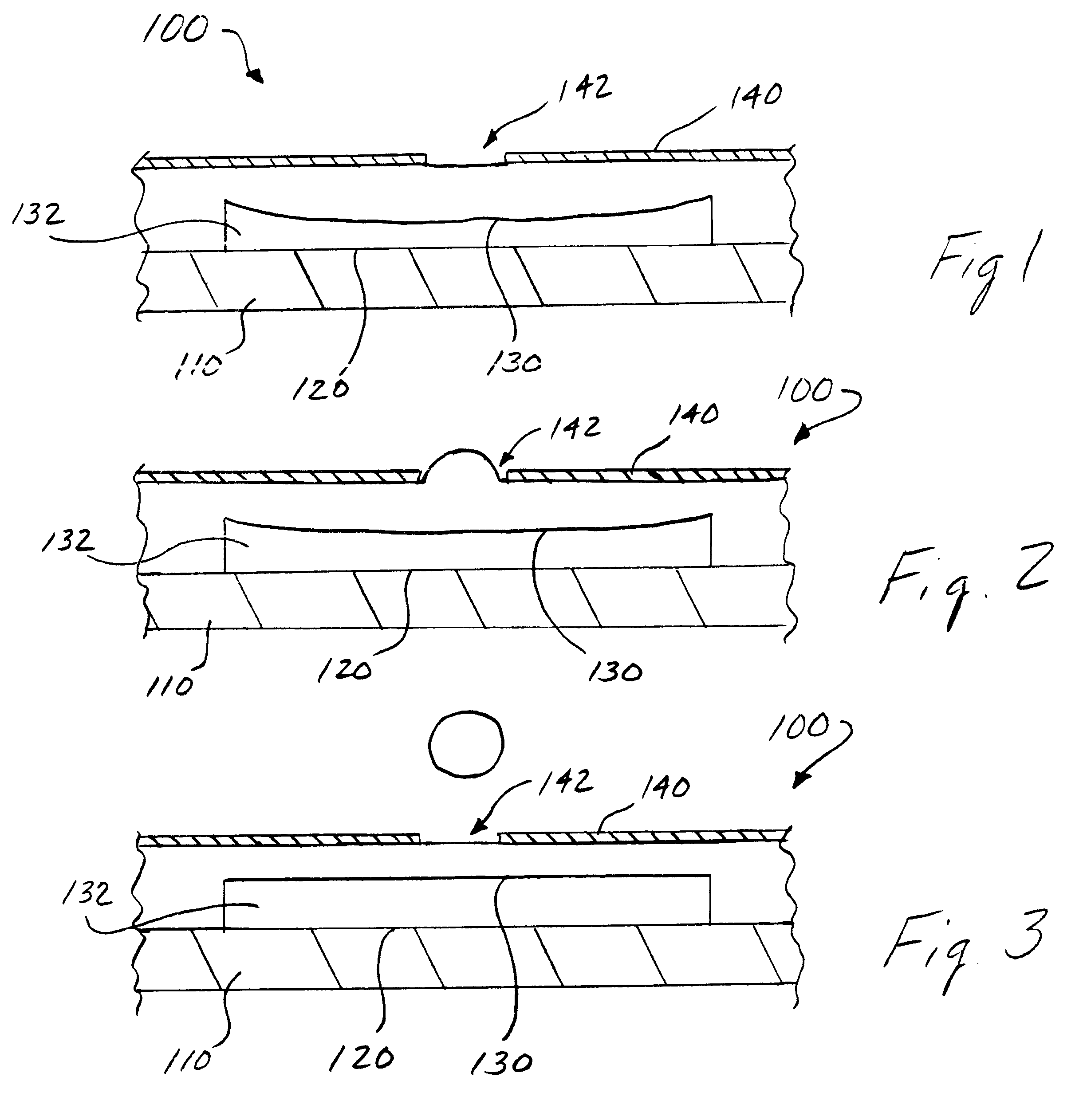
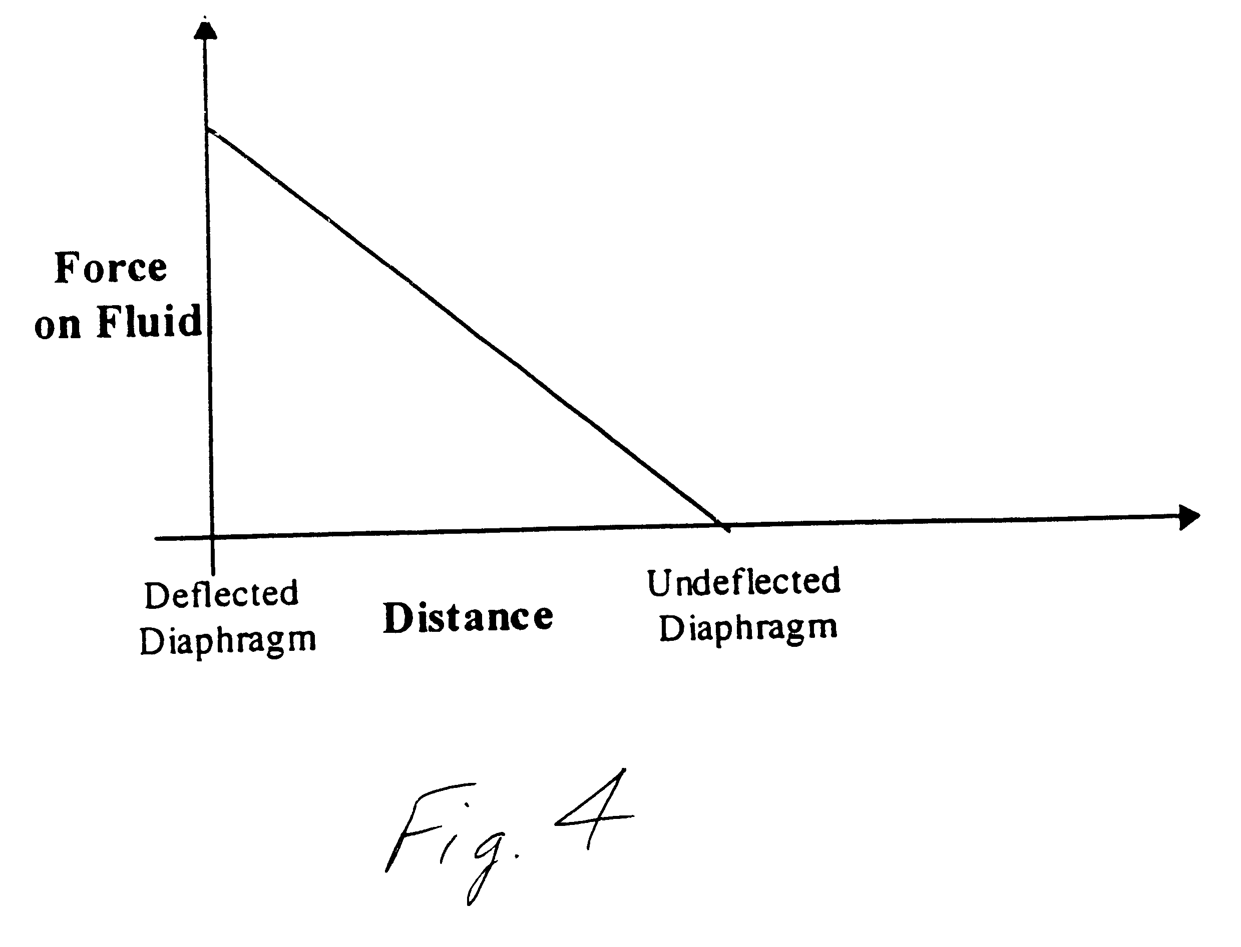
A bi-directional fluid ejector according to the systems and methods of this invention operates on the principle of electrostatic attraction. The basic features of the fluid ejector include a sealed dual diaphragm arrangement, an electrode arrangement that is parallel and opposite to the dual sealed diaphragms, and a structure which contains the fluid which is to be ejected. A diaphragm chamber containing a relatively incompressible fluid is situated behind and sealed by the diaphragms. One of the diaphragms is situated opposite a nozzle hole formed in a faceplate of the ejector. A dual electrode arrangement is advantageous, but optional. A drive signal is applied to at least one electrode of the electrode arrangement to generate an electrostatic field between the at least one electrode and a first one of the diaphragms. The first diaphragm is attracted towards the at least one electrode by an electrostatic force of the generated electrostatic field into a deformed shape. Upon deform...
PUM
 Abstract
Description
Claims
Application Information