Stator assembly for a rotary machine and clip member for a stator assembly

a stator assembly and rotary machine technology, which is applied in the direction of machines/engines, stators, liquid fuel engines, etc., can solve the problems of frequent replacement of stator vanes and frequent strikes of airfoils in the forward portion of compression sections, and achieve the effect of reducing the vibration of the van

Inactive Publication Date: 2002-06-25
RAYTHEON TECH CORP
View PDF22 Cites 120 Cited by
  • Summary
  • Abstract
  • Description
  • Claims
  • Application Information

AI Technical Summary

Benefits of technology

A primary advantage of the present invention is the restraint of a vane assembly at the inner shroud which results from a clip member moving into engagement with an inner shroud under an impact from a foreign object to restrain the tip of the vane. Another advantage is the damping of vibrations in the vane provided by a clip engaging the vane with rubbing contact.
The foregoing features and advantages of the present invention will become more apparent in light of the following detailed description of the

Problems solved by technology

The airfoils in the forward portion of the compression section are frequently struck by foreign objects that flow into the engine with the incoming stream of gases.
In addition, the stator vanes are frequently replaced over the life of the engine.

Method used


Image

  • Stator assembly for a rotary machine and clip member for a stator assembly
  • Stator assembly for a rotary machine and clip member for a stator assembly
  • Stator assembly for a rotary machine and clip member for a stator assembly

Examples


Embodiment Construction

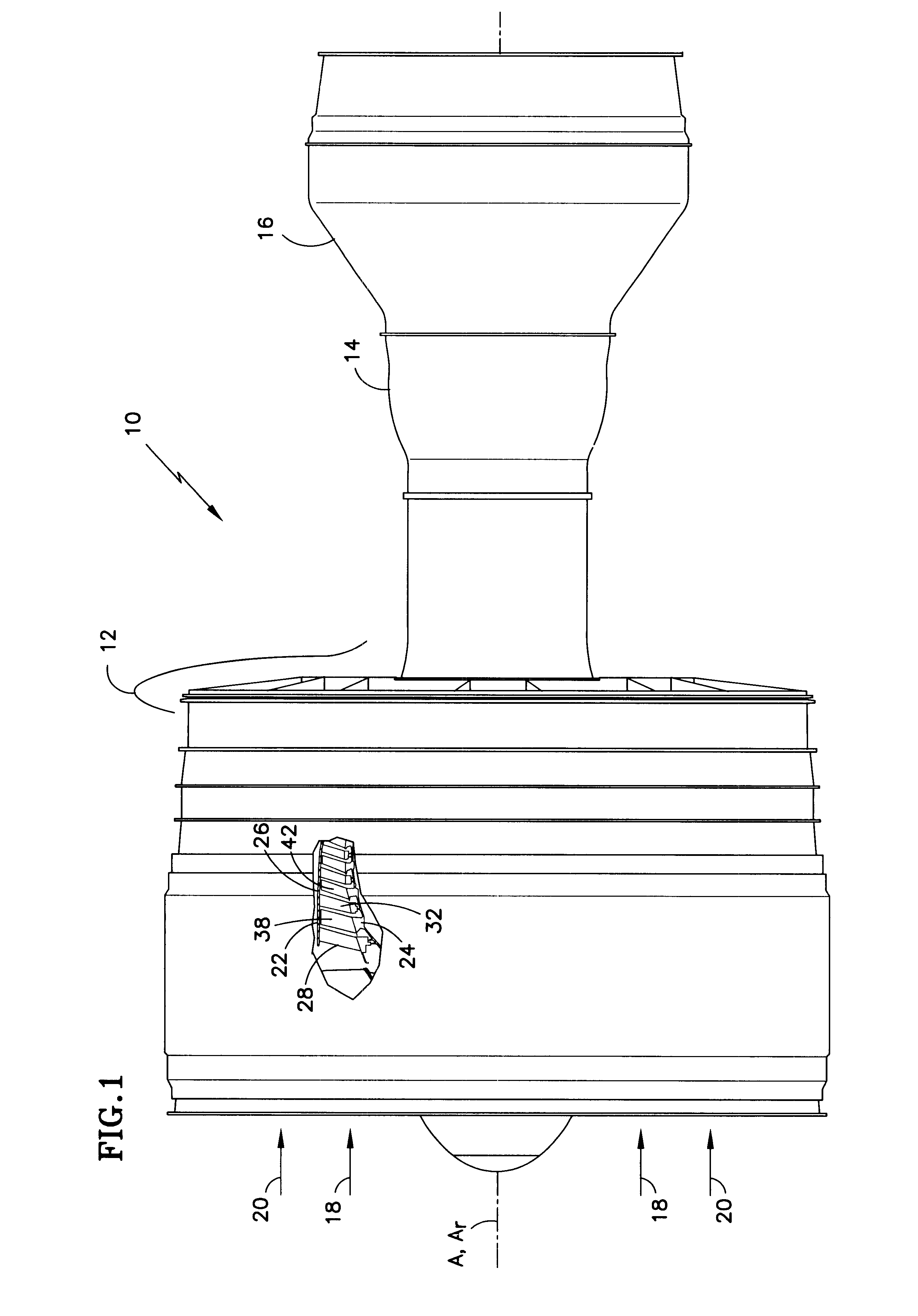
FIG. 1 is a schematic, side elevation view of a rotary machine 10, such as a turbofan gas turbine engine. The engine is disposed about an axis of symmetry A and has an axis of rotation Ar. The engine includes a compression section 12, a combustion section 14, and a turbine section 16. An annular, primary flowpath 18 for working medium gases extends axially through the sections of the engine. A by-pass flowpath 20 is outward of the primary flow path.

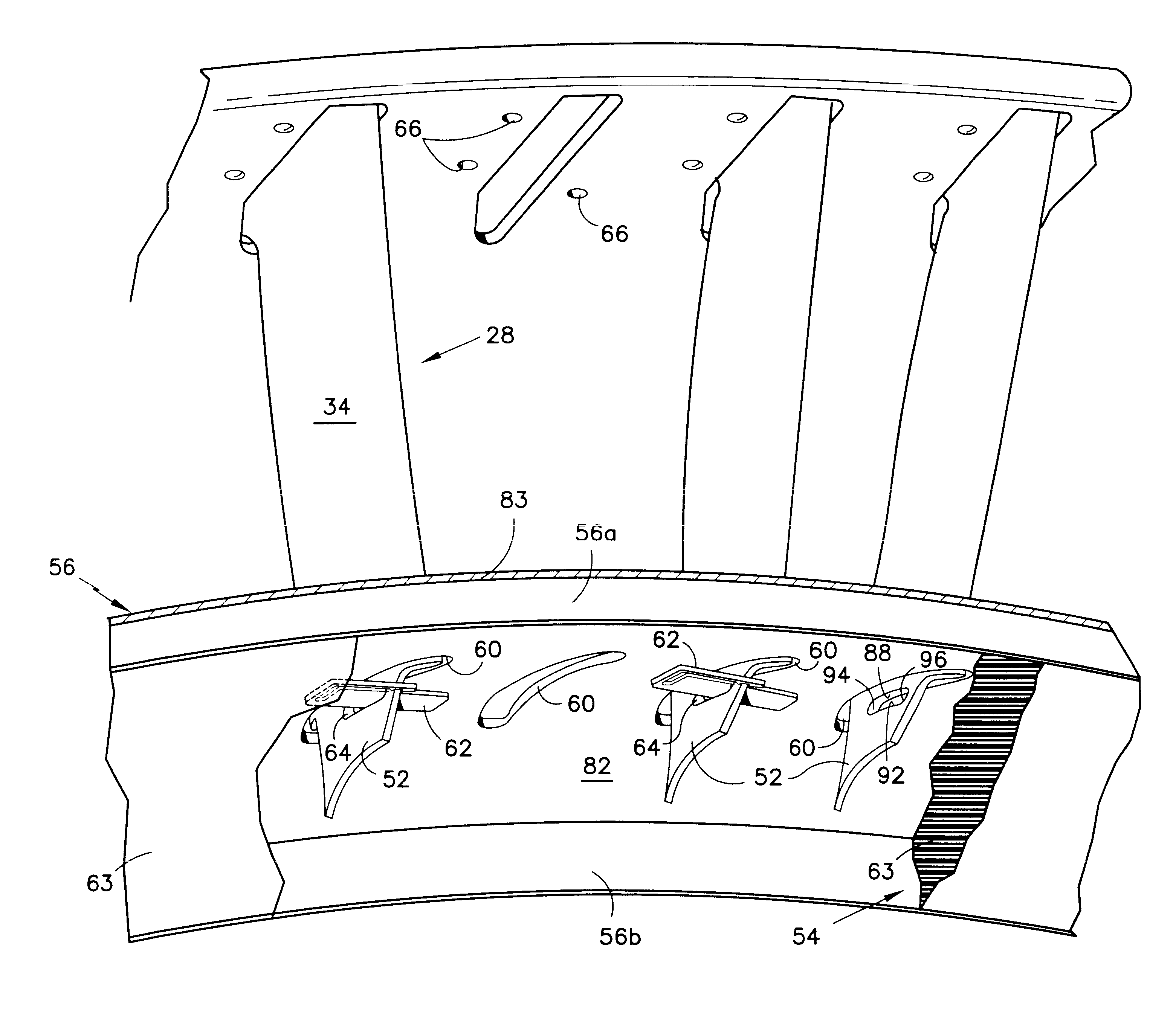
The engine is partially broken away to show a stator 22 and a rotor 24 in the compression section 12. The stator 22 includes an outer case 26 (flowpath wall) which extends circumferentially about the primary flowpath. The stator includes arrays of stator vanes, as represented by the stator vane 28 and the stator vane 32 in the compression section. The rotor has arrays of rotor blades, as represented by the rotor blade 38 and the rotor blade 42.

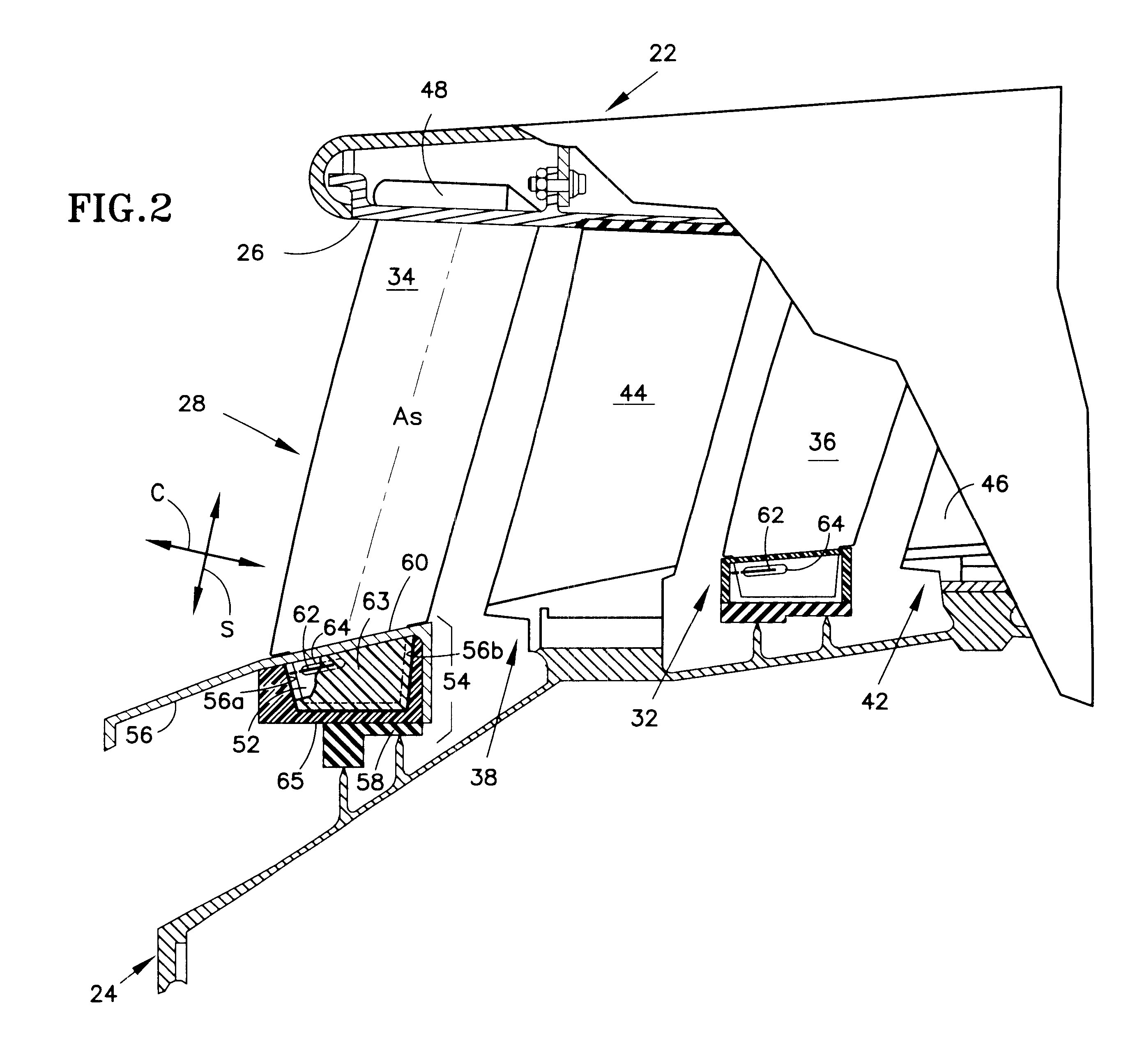
FIG. 2 is an enlarged side elevation view of a portion of the engine shown in FIG. 1 which is pa...


PUM

PropertyMeasurementUnit
modulus of elasticityaaaaaaaaaa
yield strengthaaaaaaaaaa
temperatureaaaaaaaaaa

Abstract

A stator assembly for a rotary machine having a shroud for a stator vane is disclosed. Various construction details are developed which limit movement of the stator vane into the flowpath by reason of the stator vane being restrained by the shroud. In one particular embodiment, a clip member extends through an opening in the tip of the vane and is disposed at a location adjacent a nonflowpath surface of the shroud to restrain the tip of the vane against inward movement through the shroud.

Description

This invention relates to a stator structure of the type used in rotary machines, and more specifically, to structure within the compression section to guide working medium gases through the section.An axial flow rotary machine, such as a gas turbine engine for an aircraft, has a compression section, a combustion section, and a turbine section. An annular flow path for working medium gases extends axially through the sections of the engine. The gases are compressed in the compression section to raise their temperature and pressure. Fuel is burned with the working medium gases in the combustion section to further increase the temperature of the hot, pressurized gases. The hot, working medium gases are expanded through the turbine section to produce thrust and to extract energy as rotational work from the gases. The rotational work is transferred to the compression section to raise the pressure of the incoming gases.The compression section and turbine section have a rotor which extend...

Claims


Application Information

Patent Timeline
Patent Type & Authority Patents(United States)
IPC IPC(8): F01D5/00F01D5/30F01D9/04F01D25/24F04D29/54
CPCF01D5/3023F01D9/042F01D25/246F05D2300/133Y02T50/673F05D2230/60Y02T50/60
Inventor MCMAHON, MICHAEL E.RICHARDSON, ROBERT B.FEIGLESON, STEVEN J.HONDA, KEITH T.DEMERS, CHRISTOPHER G.SERVADIO, MICHAEL A.WALTON, KEVIN A.
Owner RAYTHEON TECH CORP
Why Eureka
Try Eureka