Sear and sear spring assembly for semiautomatic handguns

a semi-automatic and spring technology, applied in the field of semi-automatic handguns, can solve the problems of inaccurate shooting and trigger creep

Inactive Publication Date: 2002-07-02
STRAYER SANDY L
View PDF7 Cites 44 Cited by
  • Summary
  • Abstract
  • Description
  • Claims
  • Application Information

AI Technical Summary

Problems solved by technology

When the trigger mechanism of the handgun is actuated the friction that is developed between sliding components, particularly the main spring and the trigger bow with the disconnector element. causes a condition known as trigger creep, which is an uneven movemen...

Method used


Image

  • Sear and sear spring assembly for semiautomatic handguns
  • Sear and sear spring assembly for semiautomatic handguns
  • Sear and sear spring assembly for semiautomatic handguns

Examples


Embodiment Construction

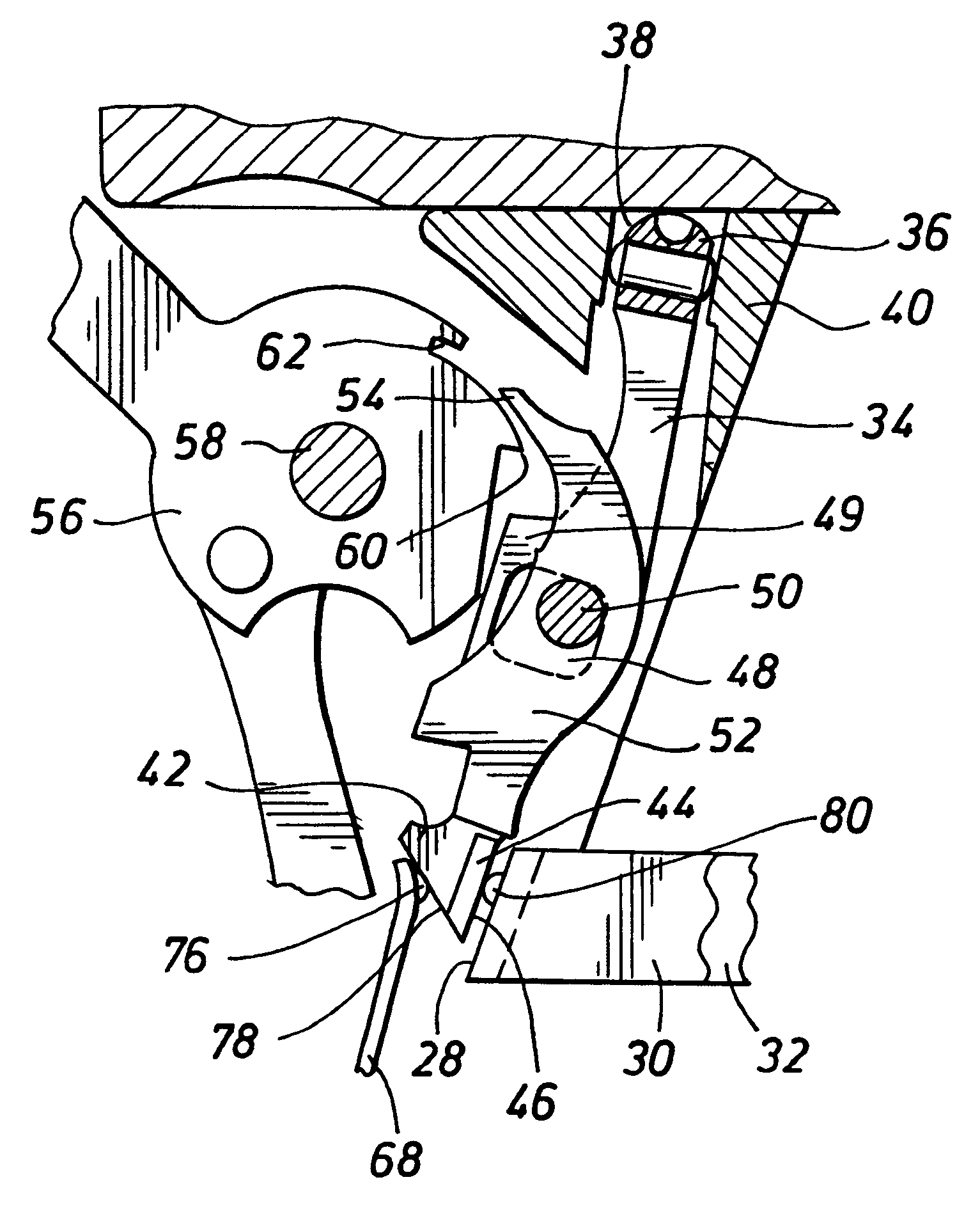
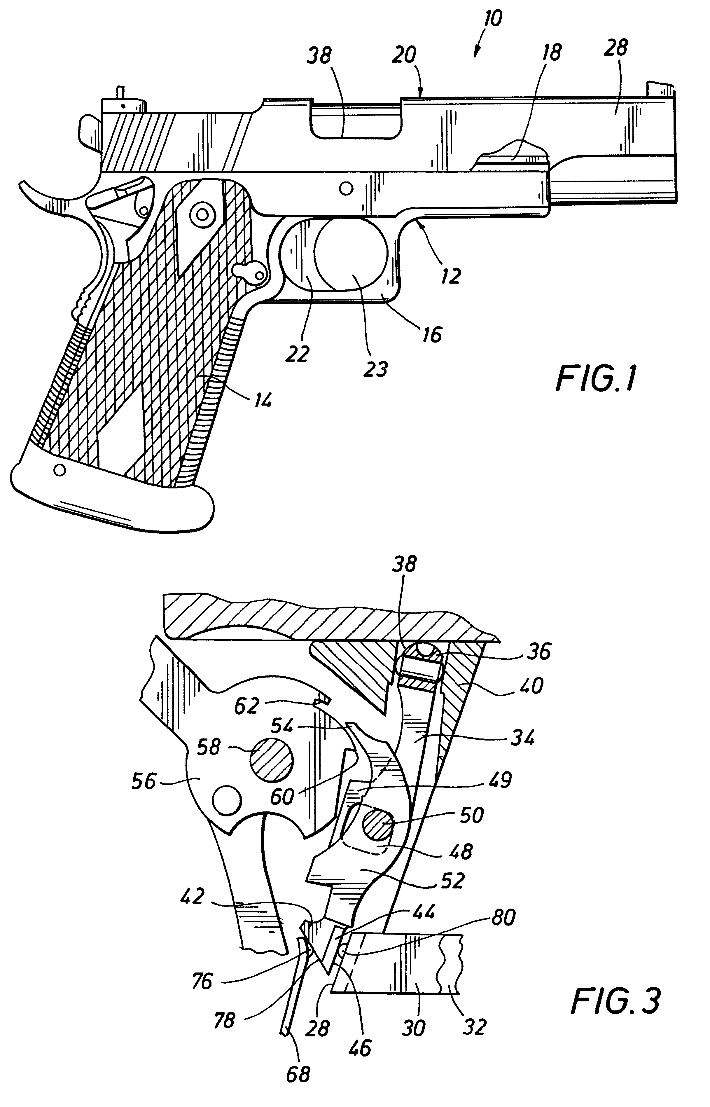
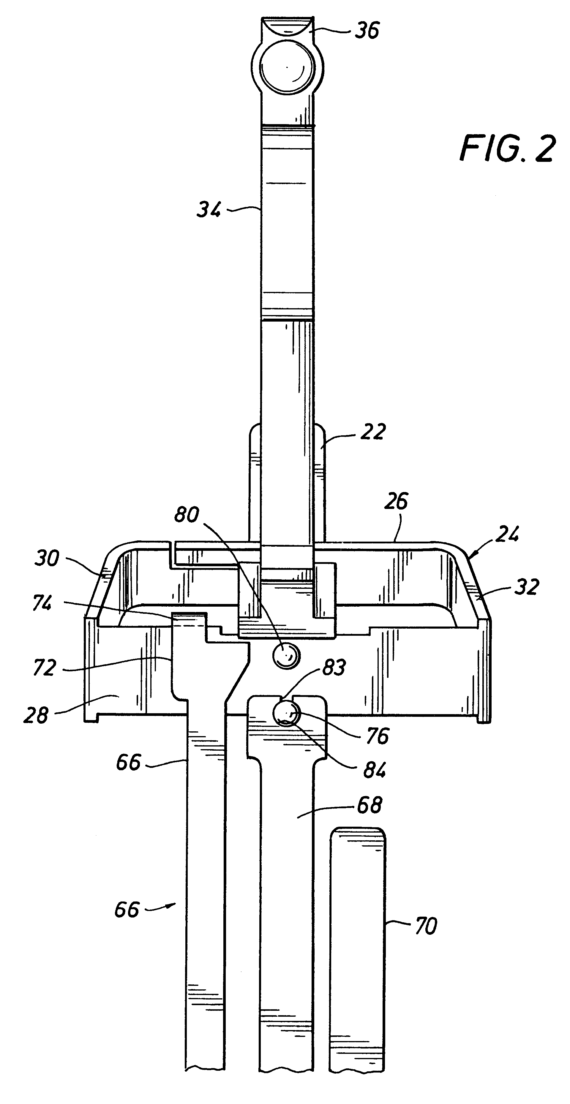
Referring now to the drawings and first to FIG. 1, a 191A1 Government Model type handgun, which is manufactured according to the principles of the present invention and represents the preferred embodiment of the invention, is shown generally at 10 and comprises a frame structure shown generally at 12 having a handgrip 14 and a trigger guard 16. The upper portion of the frame structure defines guide rails, a portion of which being shown at 18. A slide assembly, shown generally at 20 defines internal opposed guide grooves which receive the guide rails 18 and establish a guided reciprocating relation between the slide assembly and the frame of the handgun. The slide assembly 20 is generally constructed according to the principles of a conventional 1911A1 Government Model type handgun and generally incorporates the internal mechanically operable components thereof.

The handgun frame 12 defines a trigger slot opening to the trigger guard 16 and a trigger assembly is movably located within...


PUM


Abstract

A friction minimizing element such as a smooth hardened ball, a dimple in the sear spring (steel, stainless, plastic, carbon fiber or titanium material) is employed to minimize sliding friction between the spring and the disconnector or between other sliding components of a firearm mechanism, particularly the trigger mechanism of a handgun or other firearm. In addition, the same technology can be applied to the trigger bow of a semi-automatic handgun by placing an additional ball or dimple in the trigger bow that minimizes sliding friction between the rear transverse element of the trigger bow and the disconnector of the trigger mechanism. The benefits of the sear spring or the trigger bow modifications can be applied together or separately in the trigger mechanism. Each adds an individual benefit of minimizing sliding friction between engaging trigger components and thus preventing trigger creep as the trigger mechanism is actuated.

Description

1. Field of the InventionThis invention relates generally to semi-automatic handguns of the type generally referred to as the 1911A1 Government Model Handgun, which for many years has been manufactured for and utilized by military and law enforcement agencies of the United States and have also been widely available for civilian use. More specifically, the present invention concerns improvements to the basic 1911A1 Government Model Handgun to enhance the accuracy thereof for utilization of such handguns in match type shooting activities. Even more specifically, the present invention concerns imposition of one or more friction minimizing elements, such as hard metal balls projections formed by dimpling sheet metal or by any other suitable means, which establish contact points between movable handgun actuation components, particular trigger mechanisms to permit low friction, extremely smooth movement and enhancing shooting accuracy.2. Description of the Prior ArtIn a conventional 1911A...

Claims


Application Information

Patent Timeline
IPC IPC(8): F41A19/45F41A19/12F41A19/00
CPCF41A19/12F41A19/45
Inventor STRAYER, SANDY L.
Owner STRAYER SANDY L
Why Eureka
Try Eureka