

Igniter assembly actuated by parachute deployment, and flare containing the same
Inactive Publication Date: 2002-07-02
NORTHROP GRUMMAN INNOVATION SYST INC
View PDF18 Cites 11 Cited by
- Summary
- Abstract
- Description
- Claims
- Application Information
AI Technical Summary
Benefits of technology
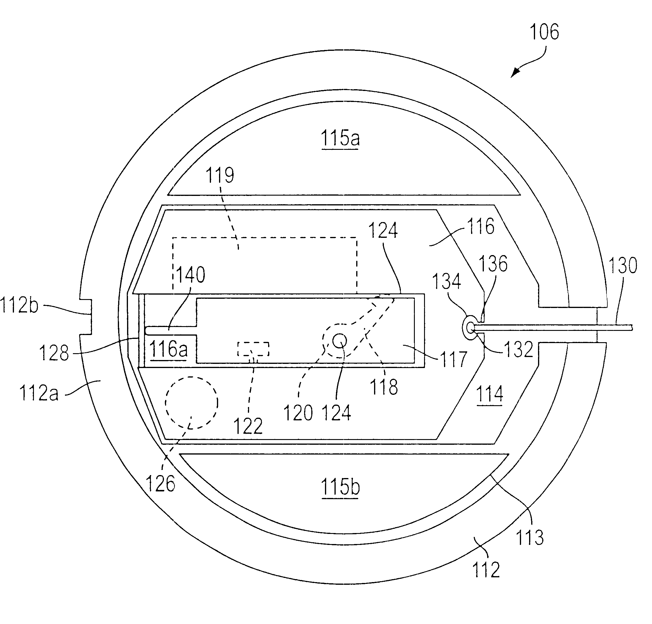
Referring to FIG. 1, the igniter 106 includes a housing 112 formed of a molded piece of LEXAN (polycarbonate). The housing 112 has longitudinally extending internal walls 113, which are receivable into an aluminum cap 150 (FIG. 4) of the casing so that peripheral portion 112a of the housing 112 abuts the periphery of the aluminum cap 150. Groove 112b assists in aligning the housing 112 and the aluminum cap 150 with the flare body. The internal walls 113 define a top hollow compartment 115a, a bottom hollow compartment 115b, and a diametrically extending slider raceway 114. Although the compartments 115a and 115b are optional, their presence is preferred in order to lower material costs and provide a venting feature discussed in greater detail below. A sliding mechanism (also referred to herein as a slider) 116 is disposed in the raceway 114 and is slidable along at least a portion of the raceway 114. In a preferred embodiment, the slider 116 is capable of sliding about 0.5 inches (about 1.27 cm) along the raceway 114. Each of the internal walls 113 defining the raceway 114 has a depth (perpendicular to the plane of FIG. 1) set substantially equal to the depth of the sliding mechanism 116.
The slider 116 is operatively connected to the parachute via cable (or lanyard) 130, which extends along an axial channel (not shown) contained in the flare body. The cable 130 is attached to the slider 116 via a swage ball 132, which is accommodated within recess 134 of the slider 116 for securing the cable 130 to the slider 116. The recess 134 is in communication with a slot 136, which is sufficiently wide to permit passage of the cable 130, but sufficiently narrow to obstruct passage of the swage ball 132 therethrough. Preferably, the cable 130 is aligned with the longitudinal axis (center) of the slider 116. Instead of using a roller pin to redirect the cable 130 near the end of the flare, a LEXAN molded surface having a relatively large radius can be used to redirect the cable 130 towards the longitudinal axis of the slider 116. Enlarging of the turn radius reduces the likelihood of cable 130 breakage.
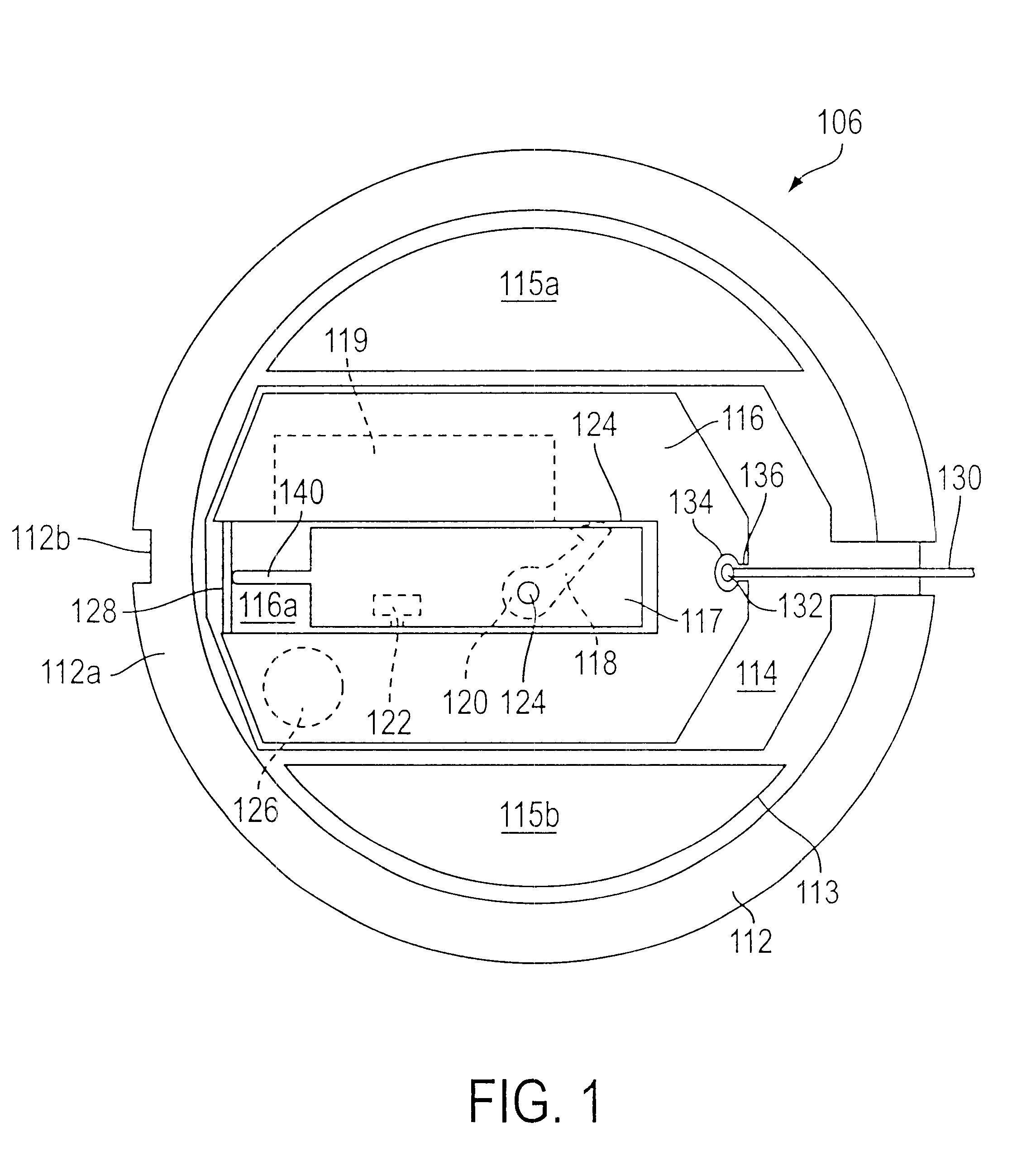
In operation, the igniter 106 is actuated by the force generated upon parachute deployment. Upon actuation of the parachute, the cable 130 is pulled with the deploying parachute. When properly operated, the force imparted on the cable 130 by the deploying parachute is sufficient to cause the cable 130 to pull the slider 116 from its loaded state to its firing state while simultaneously breaking motion restricting bridge 128 along the stationary cutter 140. After the bridge 128 has been broken, the bridge segments (designated by reference numerals 128a and 128b in FIG. 2) flare over the cutter 140 and keep the slider 116 from moving backwards (i.e., towards its loaded state position). The cutter 140 is preferably designed with a small radius on the tip rather than a sharp edge, so that over time the edge of the cutter 140 will not wear throught the bridge 128 due to normal vibrations experienced during transportation of the flare.
Movement of the slider 116 into the firing state depicted in FIG. 2 moves the striker arm 118 out of contact with cocking wall portion 124 and aligns the striker arm 118 with striker pin clearance slot 119. As shown in FIG. 3, the cocking wall portion 124 can contain a guide slot 124a for receiving the striker pin (unnumbered) at the distal end of the striker arm 118. Provision of this guide slot 124a prevents the tip of the striker pin from becoming embedded in the wall portion 124, thus further enhancing the reliability of the igniter. The striker arm 118 is hence permitted to move through the striker pin clearance slot 119 (due to the urging force imparted by the torsion spring 120) until the striker arm 118 strikes against the primer 122.
In identifying suitable materials for making the igniter assembly, the following criteria were taken into consideration: (a) form the igniter housing and slider from a material having a friction coefficient at least as low as LEXAN sliding against LEXAN; (b) permit inspection of igniter assembly by making housing from a transparent material; (c) provide good mating properties with aluminum case by choosing material having low coefficient of thermal expansion; and (d) select materials having high impact strength to avoid shattering, high tensile strengths to avoid breakage at cable slot, and high glass transition and distortion temperatures. Preferably, polycarbonate is selected as the material of choice for the igniter housing and polycarbonate with 7% TEFLON is selected as the material of choice for the slider.
Problems solved by technology
However, the availability and widespread use of military flares has negated this advantage somewhat, since there is an increased likelihood of opposing military forces also possessing flares.
However, the remaining force imparted to the cable 230 by parachute deployment is not always sufficient to overcome additional frictional forces at the slider / raceway interface and the interface between the cocked striker arm 218 and the cam surface 225.
Third, the distance of slider travel along the raceway is shortened.
Method used
View moreImage
Smart ImageViewing Examples

Examples
Embodiment Construction
has been provided for the purpose of explaining the principles of the invention and its practical application, thereby enabling others skilled in the art to understand the invention for various embodiments and with various modifications as are suited to the particular use contemplated. The foregoing detailed description is not intended to be exhaustive or to limit the invention to the precise embodiments disclosed. Modifications and equivalents will be apparent to practitioners skilled in this art and are encompassed within the spirit and scope of the appended claims.
Login to View More PUM
 Abstract
This parachute flare igniter assembly has a novel slider for attaining high reliability in firing efficiency. The slider moves along a raceway of an igniter assembly housing. Also disposed in the housing is a cartridge retained in a stationary state relative to the housing. The cartridge includes a stationary primer and a spring. A striker arm connected to the cartridge is movable into a cocked state in which the spring urges the striker arm towards the primer. The slider has an igniter composition chamber and a cocking wall portion, and is movable in tandem with the igniter composition chamber along at least a portion of the length of said raceway from a loaded position to a firing position. In the loaded position, the striker arm is maintained in the cocked state by the cocking wall portion. In the firing position, the igniter composition chamber is aligned and in communication with the primer and the striker arm is free of the cocking wall portion to permit the spring to drive the striker arm from the cocked state into the primer with the force sufficient to detonate the primer.
Description
1. Field of the InventionThis invention relates to a novel igniter assembly for igniting combustible compositions in a highly reliable manner, and in particular to an igniter assembly which includes a combustible illuminant composition and as actuated by deployment of an associated parachute. This invention also relates to devices comprising the novel igniter assembly, such devices including, by way of example, illuminating flares.2. Description of the Related ArtAmong the various environments in which illuminating flares are used, perhaps the most common environment for the use of flares involves the illumination of military battle grounds. In such applications, the flares are launched above ground or water areas suspected to contain enemy personnel and vehicles. Essentially, the illumination provided by the flare facilitates visual detection of the enemy personnel and vehicles, thereby providing more precise identification of target locations at which to aim arsenal. The illuminat...
Claims
Login to View More Application Information
Patent Timeline
 IPC IPC(8): F42C7/12F42C15/00F42C15/184F42C7/00F42B4/12F42C15/16
CPCF42C7/12F42C15/16F42C15/184
InventorANDERSON, DEREK C.POND, MARK H.OSTERHOUT, RYAN D.
OwnerNORTHROP GRUMMAN INNOVATION SYST INC