Damming device for erecting a liquid-damming protective bank

a technology of protective bank and damming device, which is applied in the direction of dykes, artificial islands, building components, etc., can solve the problems of inconvenient handling, inconvenient maintenance, and inconvenient installation,

Inactive Publication Date: 2002-07-02
MELIN SIGURD
View PDF15 Cites 26 Cited by
  • Summary
  • Abstract
  • Description
  • Claims
  • Application Information

AI Technical Summary

Problems solved by technology

Furthermore, the device is easily and flexibly pliable, which means that the device may advantageously be used in order to dam water on soft and uneven surfaces, which may have inferior bearing capacity.
However, depending on the field of use, the known damming device is also associated with certain disadvantages.
Thus, a disadvantage is that the flexible casing, made of plastic or rubber, runs the risk of being punctured at careless handling.

Method used


Image

  • Damming device for erecting a liquid-damming protective bank
  • Damming device for erecting a liquid-damming protective bank
  • Damming device for erecting a liquid-damming protective bank

Examples


Embodiment Construction

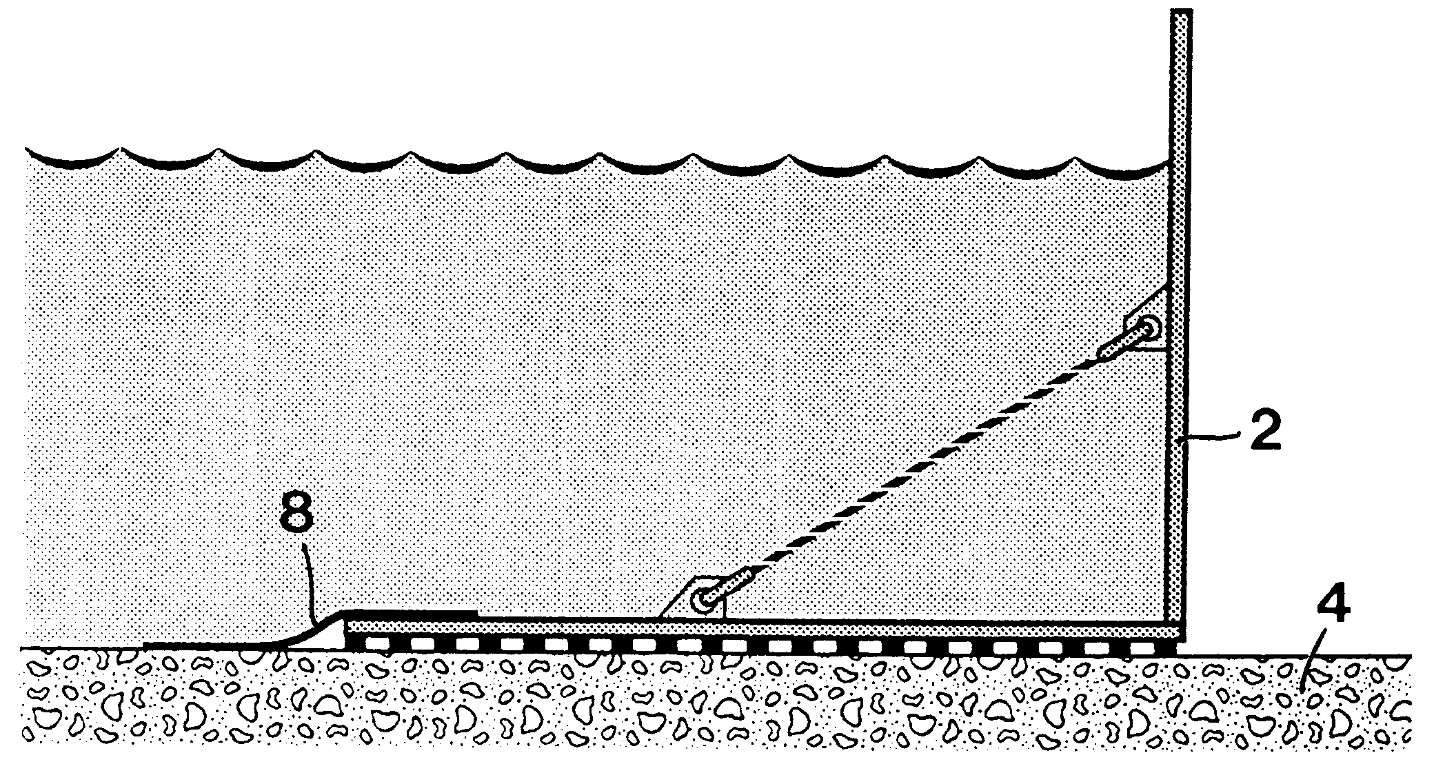
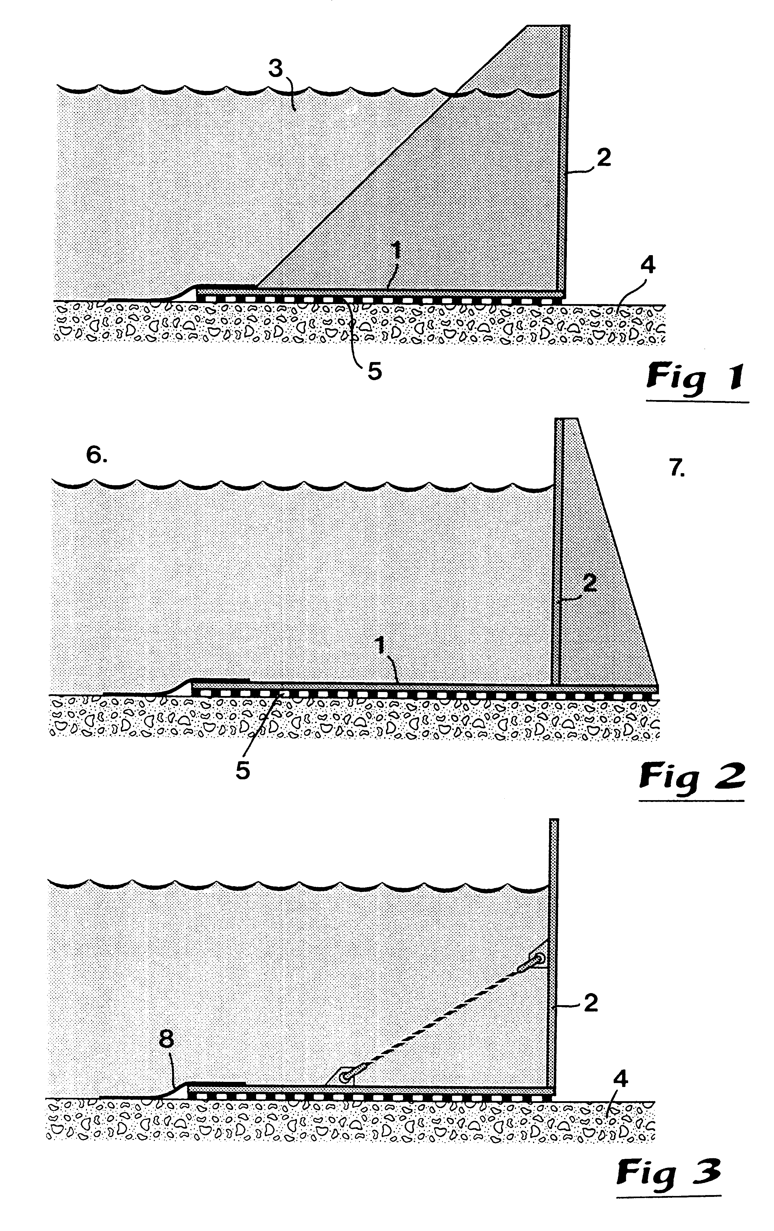
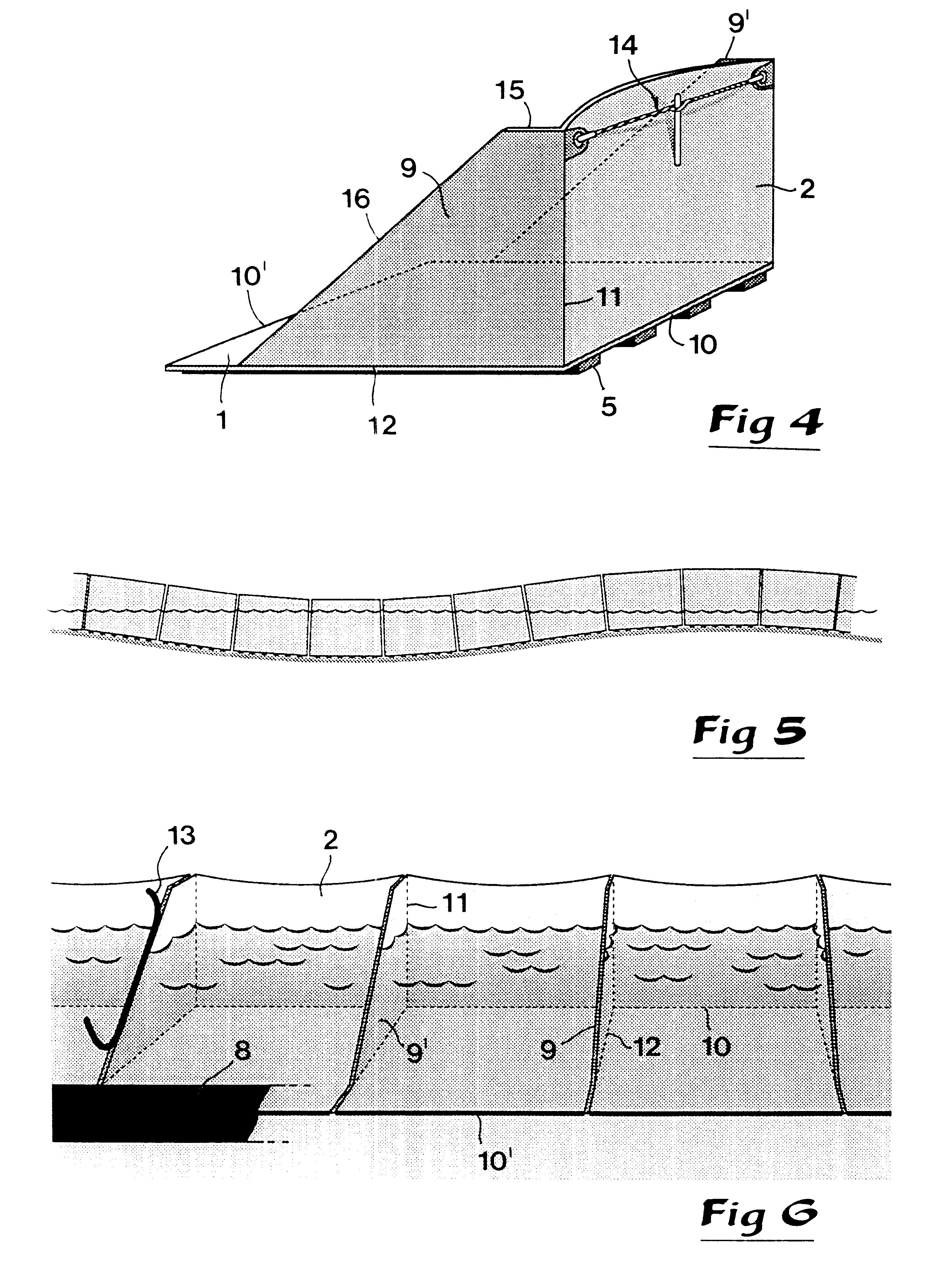
FIGS. 1-3 illustrate three different embodiments of the invention, which all have in common that they include a first, laying board 1 and a second up-right board 2. Of these boards, the first-mentioned one has the purpose of anchoring the device in its entirety, more precisely by being urged against the ground or another surface 4 by a liquid designated 3, in particular water, while the second board 2 has to the purpose of damming the liquid mass. Common for these three embodiments is furthermore that the laying board 1 on its bottom side has means 5 for draining away water which possibly leaks in under the board. The wet side or flood side of the damming device is generally designated 6, while the dry side is designated 7. The draining means 5 on the bottom side of board 1 may advantageously be in the form of a layer which extends along the entire width of the board, i.e. from the flood side to the dry side, although it is also conceivable to limit the width of the draining layer t...


PUM


Abstract

A damming device for forming a liquid-damming protective bank comprises at least one first board (1), in the active state laying, intended to be urged by the liquid against the surface and thereby anchoring the device, as well as at least a second board (2), in the active state up-right, intended to dam the liquid. There are liquid-draining means (5) on the bottom side of the anchoring board (1). Devices (9, 9') act between the two boards (1, 2) with the purpose of inhibiting tilting of the damming board (2) from the active position in the direction towards the dry the side, when liquid simultaneously affects the anchoring board (1) with a vertical force and the damming board (2) with a horizontal force.

Description

This invention relates to a damming device intended for forming a liquid-damming protective bank, which comprises components with the purpose of holding the device anchored against a surface, more precisely by friction action as a consequence of a vertically directed hydraulic pressure urging the device against the surface, as well as counteracting that liquid streams from a wet side or flood side to a dry side, means being provided between the surface and the actively acting protective bank for the purpose of draining away flood liquid which possibly leaks in under the device from the flood side so as to hold the surface on the bottom side of the device extending from the edge of the draining means being closest to the flood side to the dry the side at or close to atmospheric pressure with the purpose of achieving a maximum pressure difference in relation to the hydraulic pressure holding the device urged against the surface.PRIOR ARTA damming device of the kind generally described...

Claims


Application Information

Patent Timeline
IPC IPC(8): E02B3/10E04F13/21E02B3/04E02B7/02E02D29/02E04B2/02E04B2/06E04B2/12E04F13/08E04F13/14
CPCE02B3/108E02D29/025E04F13/0864E04B2/12E04B2002/0204E04B2002/0234E04B2002/026E04B2002/0263E02B3/106
Inventor MELIN, SIGURD
Owner MELIN SIGURD
Why Eureka
Try Eureka