
Optical glass and optical product

a technology applied in the field of optical glass and optical products, can solve the problems of difficult to adjust the weight of the glass gob, the inability to obtain the desired optical properties of the inability to obtain the optical product from the glass gob

Inactive Publication Date: 2002-07-02
HOYA CORP
View PDF17 Cites 53 Cited by
  • Summary
  • Abstract
  • Description
  • Claims
  • Application Information

AI Technical Summary

Problems solved by technology

(i) When a glass melt is flowed down through a flow pipe to obtain a glass gob, the glass gob has striae, and as a result, an optical product having desired optical properties can be no longer obtained from the glass gob.
(ii) When a glass melt is flowed down through a flow pipe to obtain a glass gob, it is difficult to adjust the weight of the glass gob, and as a result, it is difficult to adjust the weight of an optical product to be obtained from the glass gob, or there is required an step of adjusting the weight of the optical product.

Method used


Image

  • Optical glass and optical product
  • Optical glass and optical product

Examples


example 30

(Preparation of precision-press shapeable material)

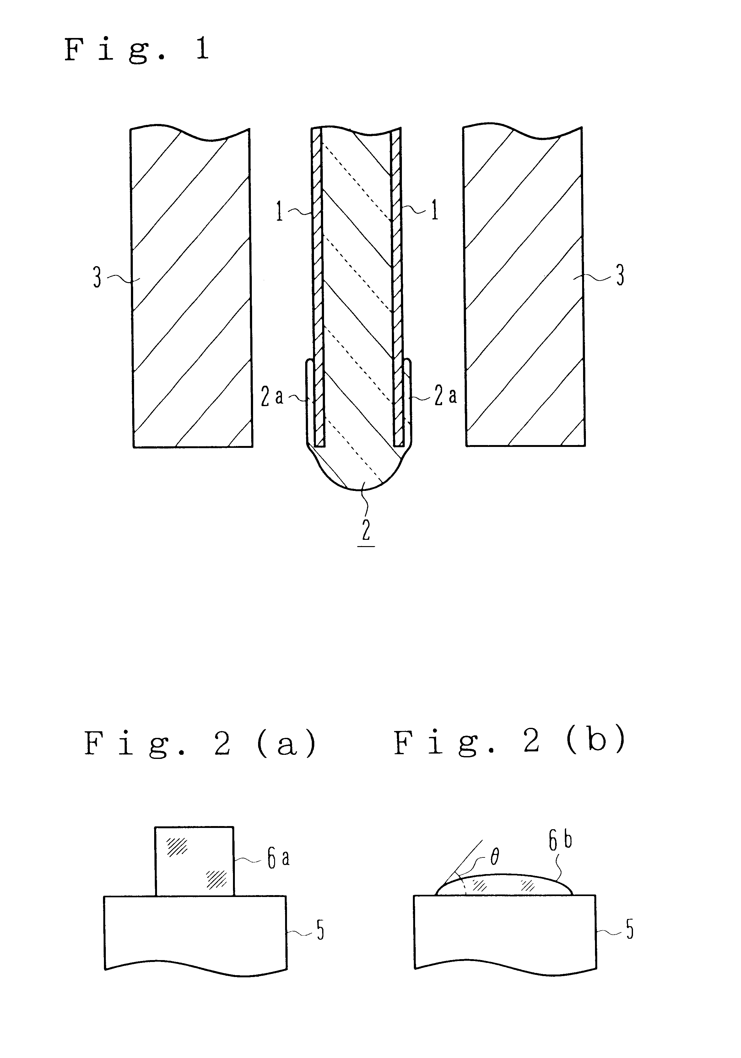
There were prepared a predetermined number of shaping molds having a concave portion shaped in a predetermined form and a gas-blowing narrow hole opened in the bottom of the concave portion each, in which the perpendicular cross section of the concave portion was opened upwardly (upwardly in a perpendicular direction during use) to have the form of a trumpet. A glass melt for an optical glass having the composition shown in Example 1 was prepared. A predetermined number of spherical shaped products were obtained from the above glass melt according to the shaping method disclosed in JP-B-7-51446.

For the above shaping, shaping conditions shown in "Experimental Results 1" in the above JP-B-7-51446 were employed. That is, the concave portion of each of the above shaping molds had a "broadening angle .theta." of 15.degree., and the above narrow holes had a diameter of 2 mm each. Further, the glass melt was directed to a site right above ...

example 31

(Preparation of Optical Product)

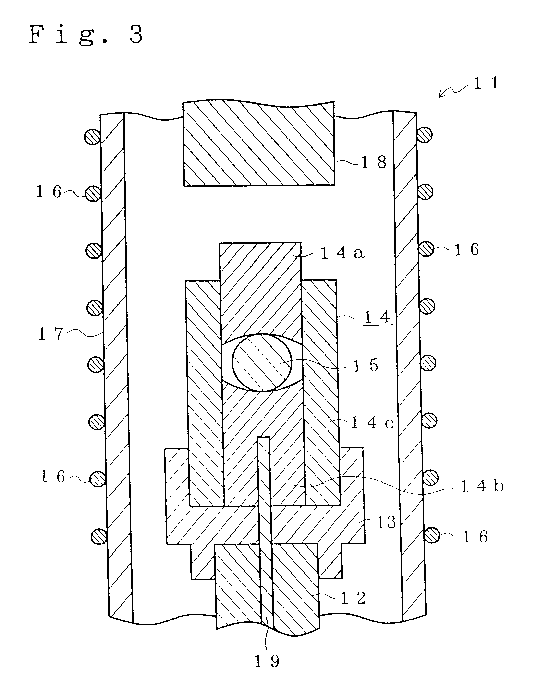
By using a shaped product obtained in Example 30 as a precision-press shapeable material, an aspherical lens having a diameter of 6.4 mm was obtained by precision-press shaping the material by means of a precision-press shaping machine shown in FIG. 3. The precision-press shaping was carried out under conditions where the shaping temperature was set at a temperature at which the above material had a viscosity (glass viscosity) of 10.sub.9 poise (10.sub.8 Pa.multidot.s), the pressing pressure was set at 180 kg / cm.sup.2 and the pressing time was set for 10 seconds.

In the precision-press shaping machine 11 shown in FIG. 3, a support block 13 is disposed in one end of a support rod 12, and a shaping mold 14 constituted of an upper mold member 14a, a lower mold member 14b and a guide mold member (sleeve) 14c is disposed on the support block 13. A shapeable material (precision-press shapeable material) 15 is placed on a shaping surface of the lower mold mem...


PUM

PropertyMeasurementUnit
Fractionaaaaaaaaaa
Fractionaaaaaaaaaa
Percent by massaaaaaaaaaa

Abstract

When a glass melt of an optical glass having a refractive index (nd) of at least 1.7 and an Abbe number (νd) of 28 to 41 is flowed down from a flow pipe made of Pt or a Pt alloy to form glass gobs continuously, there is caused a problem that the glass gobs have striae or that the weight variability among the glass gobs is large, and the problem can be overcome by the use of an optical glass comprising silicon oxide and boron oxide, the ratio of a content of the silicon oxide to a content of the boron oxide being greater than 0.78, the optical glass having a contact angle of at least 40° to Pt or a Pt alloy at a predetermined temperature equivalent to, or higher than, its liquidus temperature or in a predetermined temperature range whose lower limit is equivalent to, or higher than, the liquidus temperature and having a sag temperature Ts of 580° C. or lower.

Description

The present invention relates to an optical glass, a shapeable material formed of the above optical glass, a process for the production of the shapeable material, an optical product formed from the above optical glass as a raw material and a process for the production of the above optical product. It particularly relates to a high-dispersion or intermediate-dispersion optical glass having high refractive index, a precision-press shapeable material formed of the above optical glass, a process for the production of the shapeable material, an optical product formed from the above optical glass as a raw material and a process for the production of the above optical product.TECHNICAL BACKGROUNDFor forming a desired optical system, generally, it is required to combine various optical elements having different refractive indices n.sub.d and Abbe numbers .nu..sub.d. For this purpose, various optical glasses having different refractive indices n.sub.d and Abbe numbers .nu..sub.d have been de...

Claims


Application Information

Patent Timeline
IPC IPC(8): C03C3/062C03C3/064
CPCC03C3/064Y10S501/903Y10S501/90
Inventor SATO, KOUICHI
Owner HOYA CORP
Learn More