Meshed optical network

Inactive Publication Date: 2002-07-02
BRITISH TELECOMM PLC
View PDF5 Cites 37 Cited by
  • Summary
  • Abstract
  • Description
  • Claims
  • Application Information

AI Technical Summary

Problems solved by technology

Such an interconnection scheme however suffers from a scalability problem.
This necessitates a great deal of re-wiring and becomes more and more difficult to achieve as N becomes large.
In particular such a network lacks resilience, that is there is a serious loss of perform

Method used


Image

  • Meshed optical network
  • Meshed optical network
  • Meshed optical network

Examples


Embodiment Construction

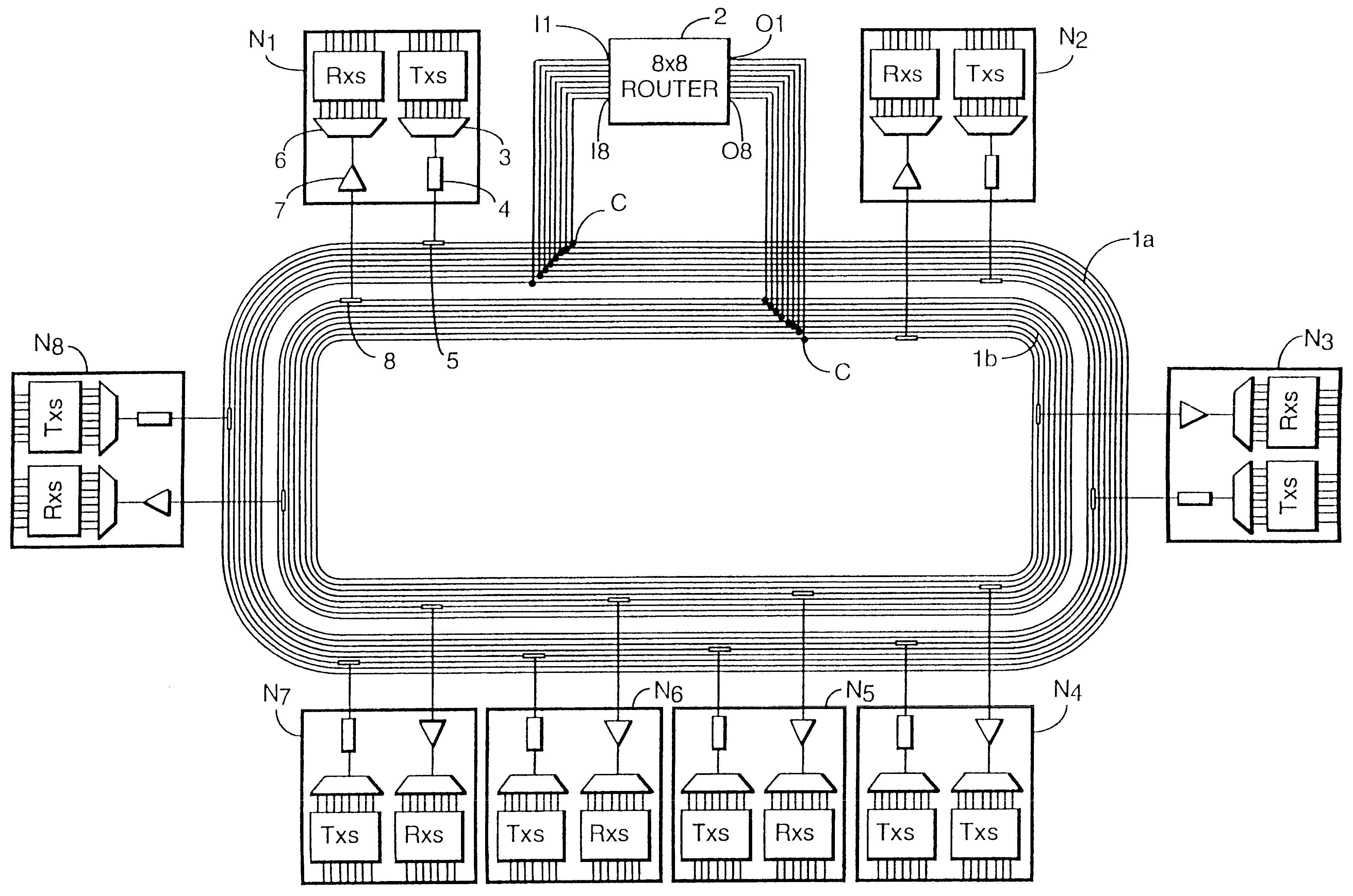
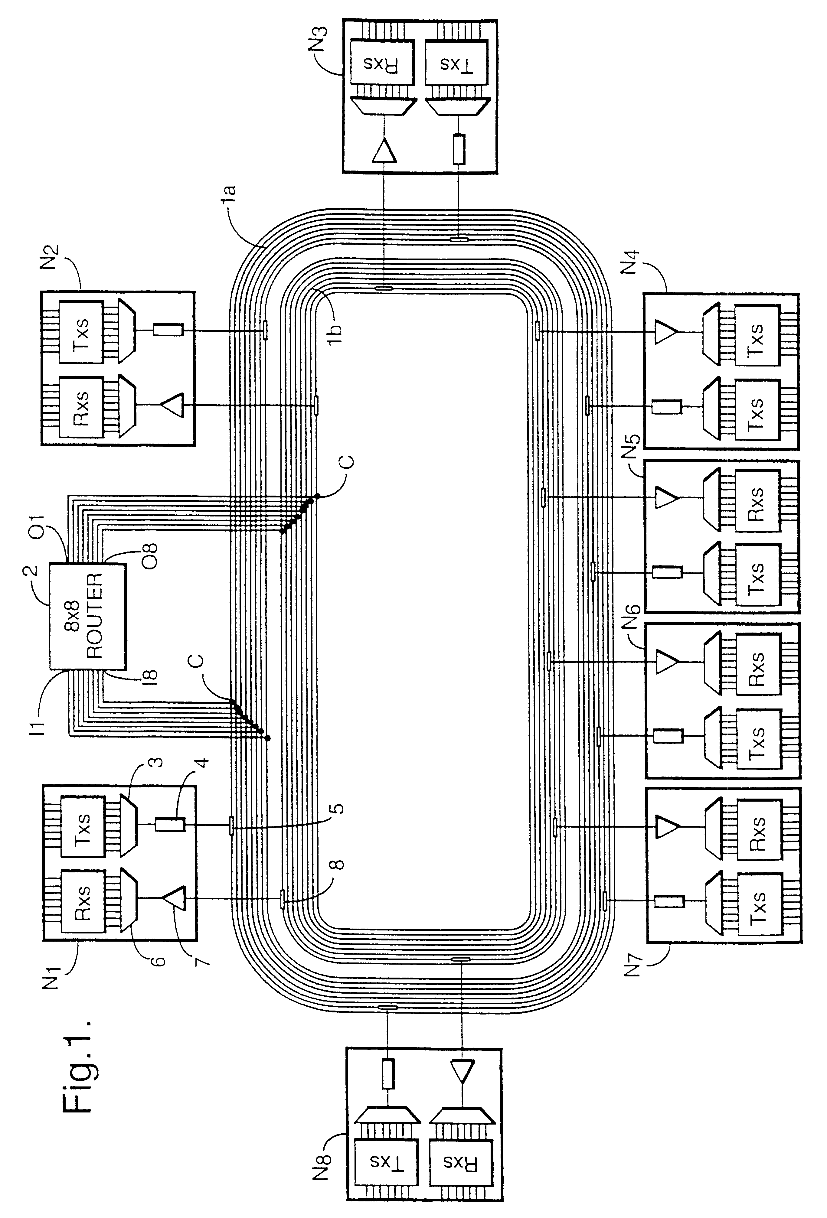
An optical network comprises eight nodes N1-N8 connected to optical waveguides 1A, 1B physically configured as a duplex ring. An 8.times.8 WDM router 2 is connected to the ring with its input side connected to the set of waveguides 1A making up the first half of the duplex ring and its output side connected to the set of waveguides 1B making up the second half of the duplex ring. Specifically, each of the eight inputs to the router I1-I8 is connected via a 50:50 coupler C to a corresponding one of the optical fibres in the first set of waveguides 1A, and on the output side each of 8 outputs O1-O8 is connected via a coupler C to a corresponding one of the eight fibres in the second set of optical waveguides 1B.

The network might be used, for example as a LAN or WAN for interconnecting computer systems, or as a telecommunications network, in which case the node transmitters / receivers are used to add / drop telecommunications traffic from a respective network switch.

Each of the nodes N1-N...


PUM


Abstract

An optical network includes interconnected via an NxN WDM router. The nodes are connected to an optical waveguide ring having a duplex structure. A first set of optical waveguides connects the transmitters in the nodes and a second set of optical waveguides connects the receivers in the nodes. The NxN wavelength router is connected across the ring between the first set of optical waveguides and the second set of optical waveguides. Each of the nodes is able to communicate with any other of the nodes on a respective wavelength channel via the router.

Description

1. Field of the InventionThe present invention relates to an optical network, and in particular to a network capable of providing fully meshed interconnection of a number of nodes. Such a network might be used, for example, for telecommunications or data communications.2. Description of Related ArtIn a fully interconnected network, each port of a given node is able to obtain direct connection to every other node. Such an interconnection scheme might be implemented by providing direct optical fibre connections between the output ports of a given node and every other node on the network and input port. For example, in a network with 4 nodes, node 1 would have three output ports with direct fibre connections to nodes 2, 3 and 4 respectively, and would have three input ports with further direct fibre connections from the outputs of nodes 2, 3 and 4, with similar patterns of connection for the other nodes. Such an interconnection scheme however suffers from a scalability problem. Adding ...

Claims


Application Information

Patent Timeline
IPC IPC(8): H04J14/02H04L12/28H04B10/27H04B10/272H04B10/275H04B10/291H04B10/80H04Q3/52
CPCH04J14/0227H04J14/0283H04J14/0286H04J14/0289H04L12/28H04J14/0241
Inventor BLAIR, LOUDON TMACKENZIE, FIONAARMITAGE, JONATHAN R
Owner BRITISH TELECOMM PLC
Why Eureka
Try Eureka