
Pressurized hose coupling

a technology of hose coupling and hose, which is applied in the direction of pipe connection arrangement, pipe/joint/fitting, and fluid pressure sealing joints. it can solve the problems of hose loosening and disconnecting, affecting the construction efficiency of the hose, so as to achieve the effect of fewer parts and simple construction

Inactive Publication Date: 2002-07-09
MARKOVIC BRANIMIR
View PDF9 Cites 27 Cited by
  • Summary
  • Abstract
  • Description
  • Claims
  • Application Information

AI Technical Summary

Benefits of technology

It is a feature of the present invention to provide a fluid pressure hose coupling which overcomes the above-mentioned disadvantage of the prior art and which is simple to construct and has fewer parts.
Another feature of the present invention is to provide a fluid pressure hose coupling wherein a flexible hose end can be easily slid over a nipple outer smooth surface, easily secured thereover and easily disconnectable from the coupling.
A still further feature of the present invention is to provide a fluid pressure hose coupling wherein the hose pressure in the line acts against the cylindrical hose clamping sleeve to assist in displacing the sleeve over the hose as the sleeve and the hose are pulled together over the nipple.

Problems solved by technology

A problem with such design is that because the nipple has ridges thereon, it is sometimes difficult to push the hose entirely over the elongated nipple and locate it into the cap cavity.
This finger force securement of the ring does not always result in a solid attachment of the flexible hose end over the nipple and could cause the hose to loosen and disconnect during use or cause leakage.
Furthermore, the inner surface of the sleeve is not parallel to the nipple outer surface and therefore only a portion of the sleeve is used to clamp the hose and making it more susceptible to leakage.

Method used


Image

  • Pressurized hose coupling
  • Pressurized hose coupling
  • Pressurized hose coupling

Examples


Embodiment Construction

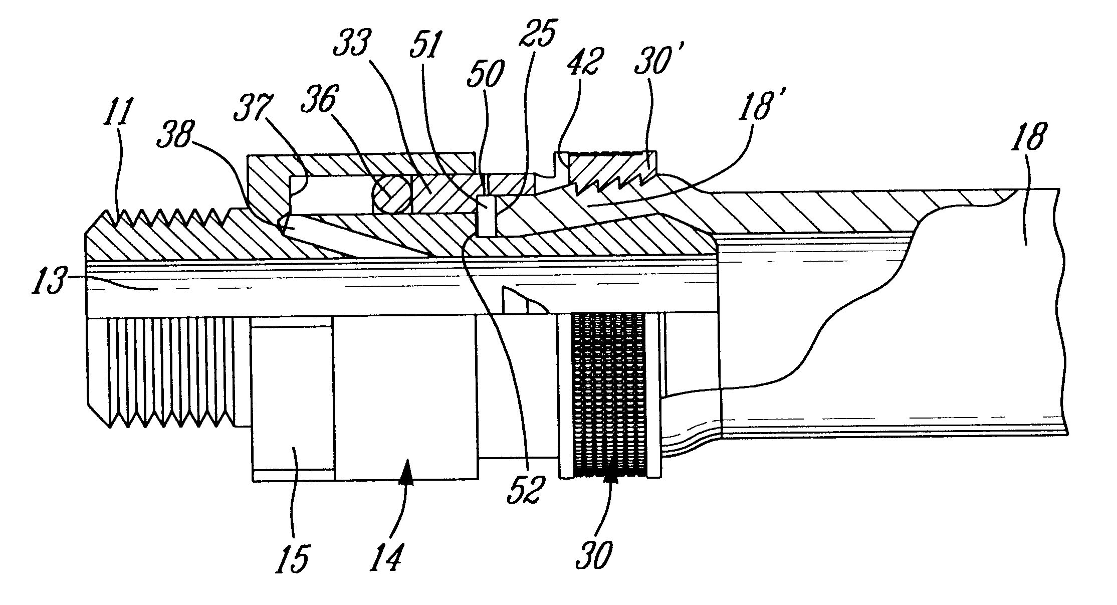
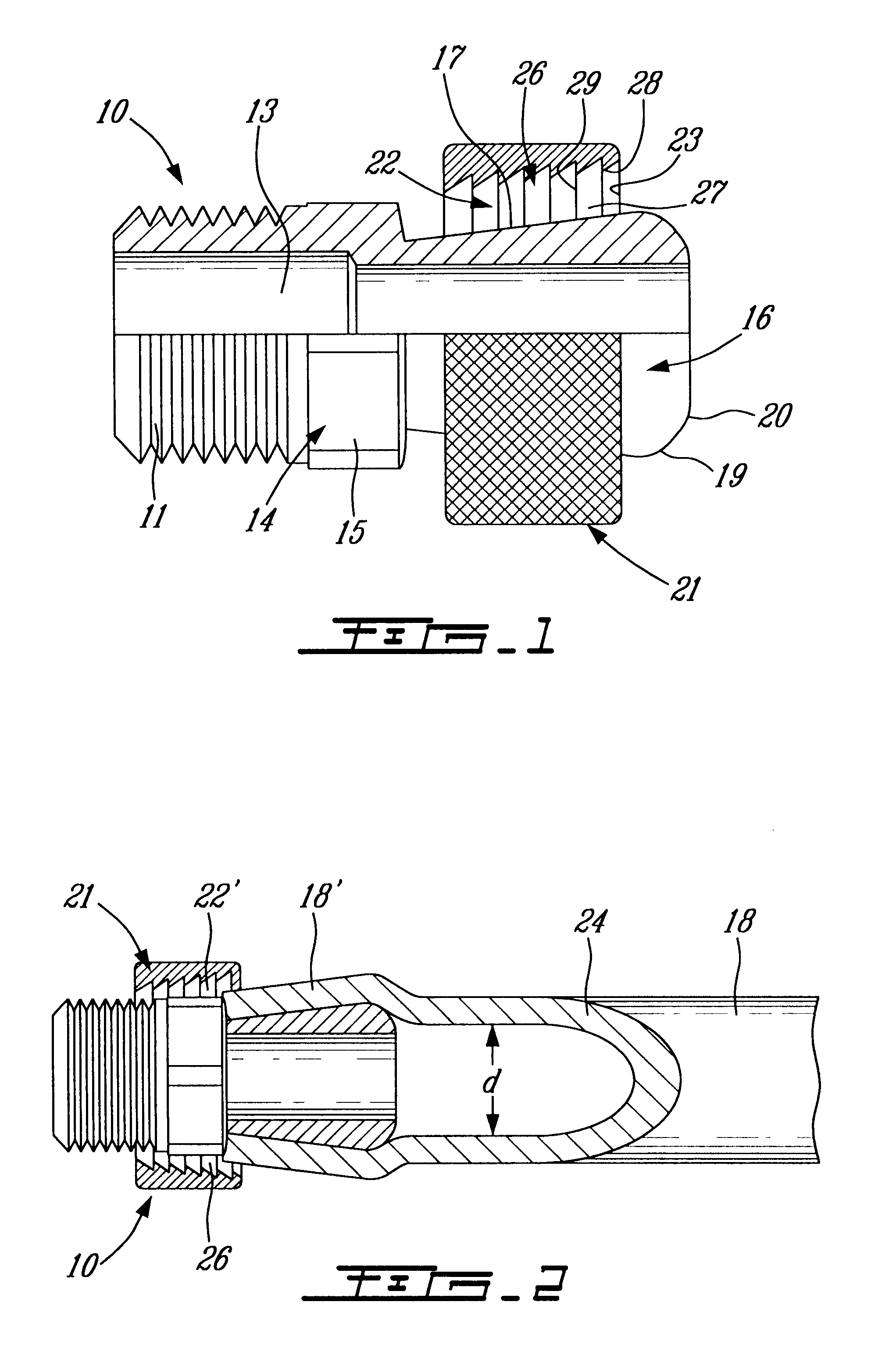
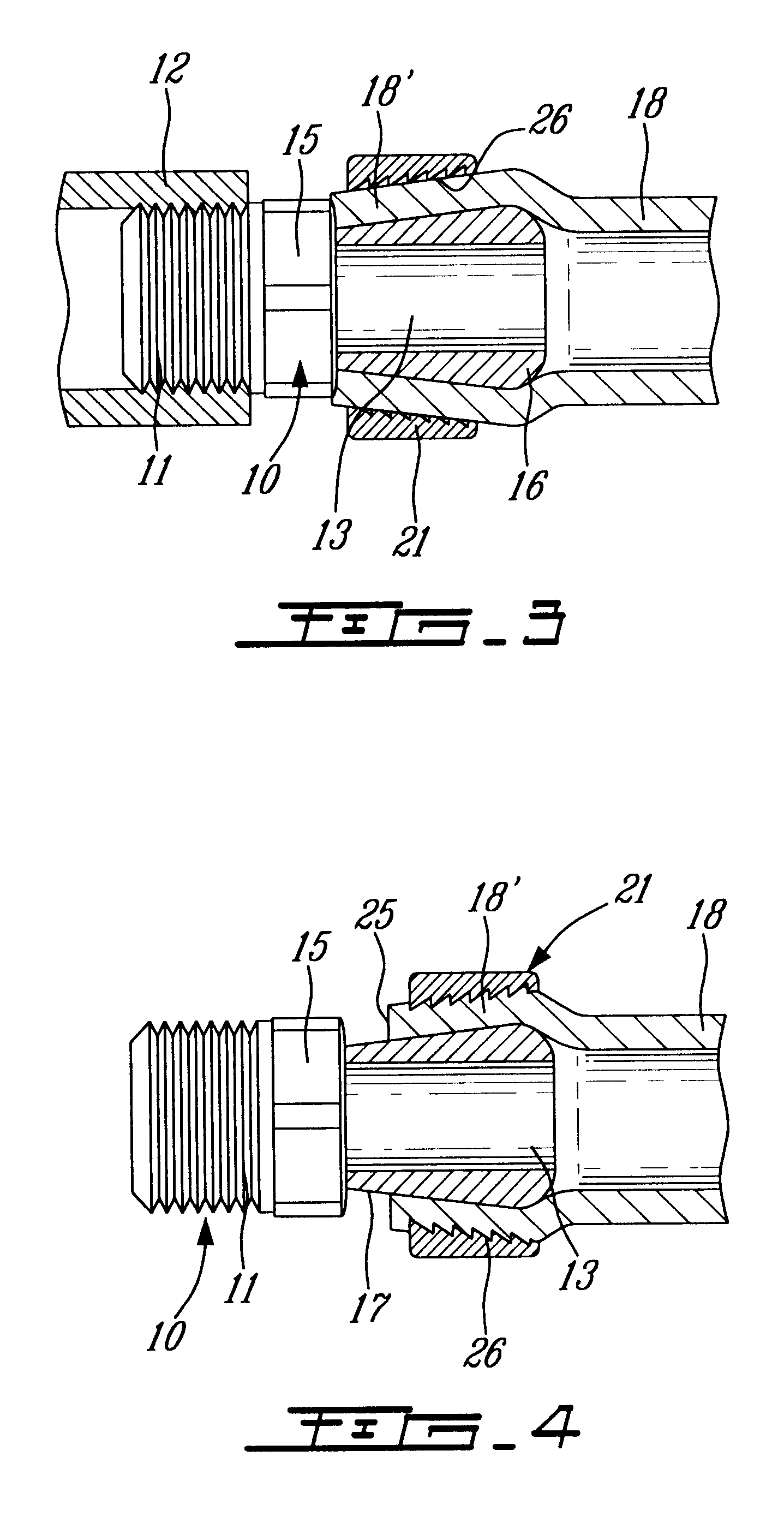
Referring now to the drawings, and more particularly to FIGS. 1 to 5, there will be described the construction and operation of the fluid pressure hose coupling 10 of a first embodiment of the present invention. As hereinshown, the coupling 10 has a threaded connecting pipe section 11 for threaded engagement with a pressure line 12, as shown in FIG. 5. A through bore 13 extends through the body 14 of the coupling. The body 14 also has a hexagon cylindrical section 15 whereby to be engaged by a tool to thread the connecting pipe section 11 in the pressure line 12.

The coupling 10 is also provided at the opposed end to the threaded pipe section 11 with a cylindrical nipple end section 16 provided with a circumferentially smooth tapered cone-line outer surface 17. This smooth surface facilitates the sliding of the end section 18' of a flexible pipe 18 thereover. As also hereinshown, the nipple end section 16 has a larger outer diameter section 19 at a free end thereof. The larger diamet...


PUM

PropertyMeasurementUnit
Thicknessaaaaaaaaaa
Pressureaaaaaaaaaa
Diameteraaaaaaaaaa

Abstract

A fluid pressure hose coupling for connecting a flexible hose to a pressurized fluid line. The coupling has a connecting end section for securement to a pressurizable line and a cylindrical nipple end section for securing an end section of a flexible hose thereto. The nipple end section has a tapered cone-like outer surface having a larger outer diameter section at a free end thereof. A cylindrical hose clamping sleeve is positionable about the nipple end section and also has an inwardly tapered inner surface whose diameter is larger at the front end thereof and wherein the inner surface of the clamping sleeve and the outer surface of the cylindrical nipple end section extend parallel to one another. By positioning a flexible hose end section over the nipple and placing the hose clamping sleeve over the hose end section and by applying pressure in the line and pulling the sleeve and hose sections together, in an outward direction, the hose end section becomes clampingly secured between the clamping sleeve and the tapered outer surface of the nipple end section. To disconnect the hose pressure is removed and the hose clamping sleeve is pushed rearwardly to clear the hose end section which may then be pulled off the nipple end. The clamping sleeve may also have a piston end located in a channel which is in communication with the pressurized fluid whereby the pressurized fluid displaces the sleeve in clamping engagement with the end section of the hose.

Description

The present invention relates to a pressurized hose coupling which is simple in construction and which uses line pressure to positively engage a flexible hose with the coupling.Various pressurized air hose couplings are known to couple a pressurized line to a flexible hose. Couplings using nipple ends and lock collars are also known and reference is made to U.S. Pat. No. 3,885,819 as a typical example of prior art couplings that resemble the type of connector to which the present invention relates. However, in that patent, the connector utilizes an end cap to receive the end of the hose fitted over the nipple. The sleeve is also dimensioned to be supported on the end cap. The nipple is provided with ridges as well as the inner surface of the ring. The end cap is also transparent to locate the end of the hose to make sure it remains immovable on the nipple.In the patent, the sleeve is hand-squeezed forwardly on the hose to connect the hose between its ridges and the ridges of the nip...

Claims


Application Information

Patent Timeline
IPC IPC(8): F16L33/22
CPCF16L33/225
Inventor MARKOVIC, BRANIMIR
Owner MARKOVIC BRANIMIR
Learn More