Magnet injector for fuel reservoir injection systems

a fuel reservoir and injector technology, applied in the direction of fuel injection apparatus, charge feed system, combustion engine, etc., can solve the problems of increasing the force of the nozzle needle, allowing only a limited armature speed, and too long switching time to enable a pre-injection replicabl

Inactive Publication Date: 2002-07-23
ROBERT BOSCH GMBH
View PDF8 Cites 10 Cited by
  • Summary
  • Abstract
  • Description
  • Claims
  • Application Information

AI Technical Summary

Problems solved by technology

This rising pressure causes an increasing force on the nozzle needle.
A disadvantage of this known magnet injector, however, is that its switching times are too long to enable a preinjection with replicable, small preinjection quantities of 1 mm.sup.3 and less.
This is because the magnet valve used allows only a

Method used


Image

  • Magnet injector for fuel reservoir injection systems
  • Magnet injector for fuel reservoir injection systems
  • Magnet injector for fuel reservoir injection systems

Examples


Embodiment Construction

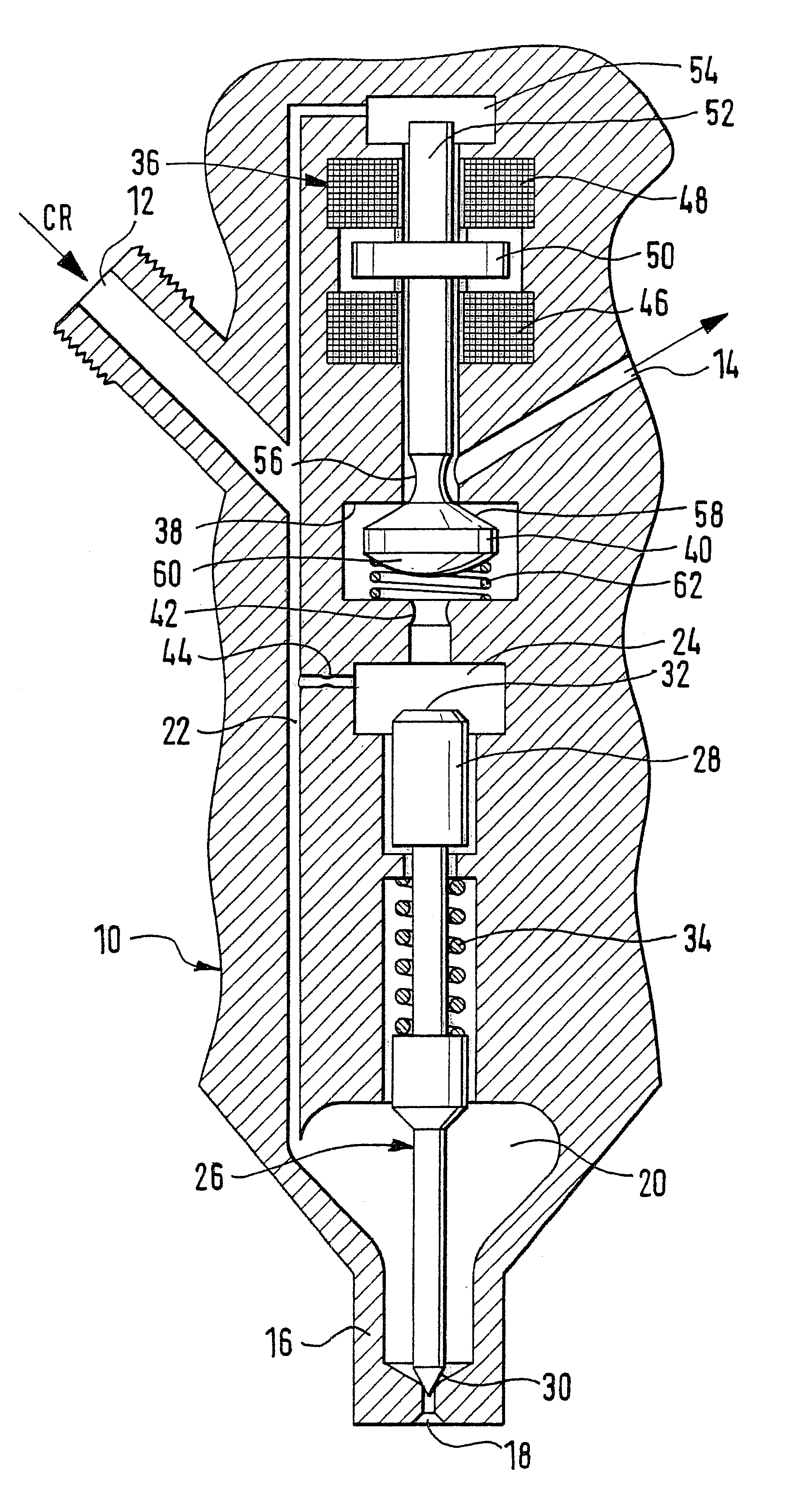
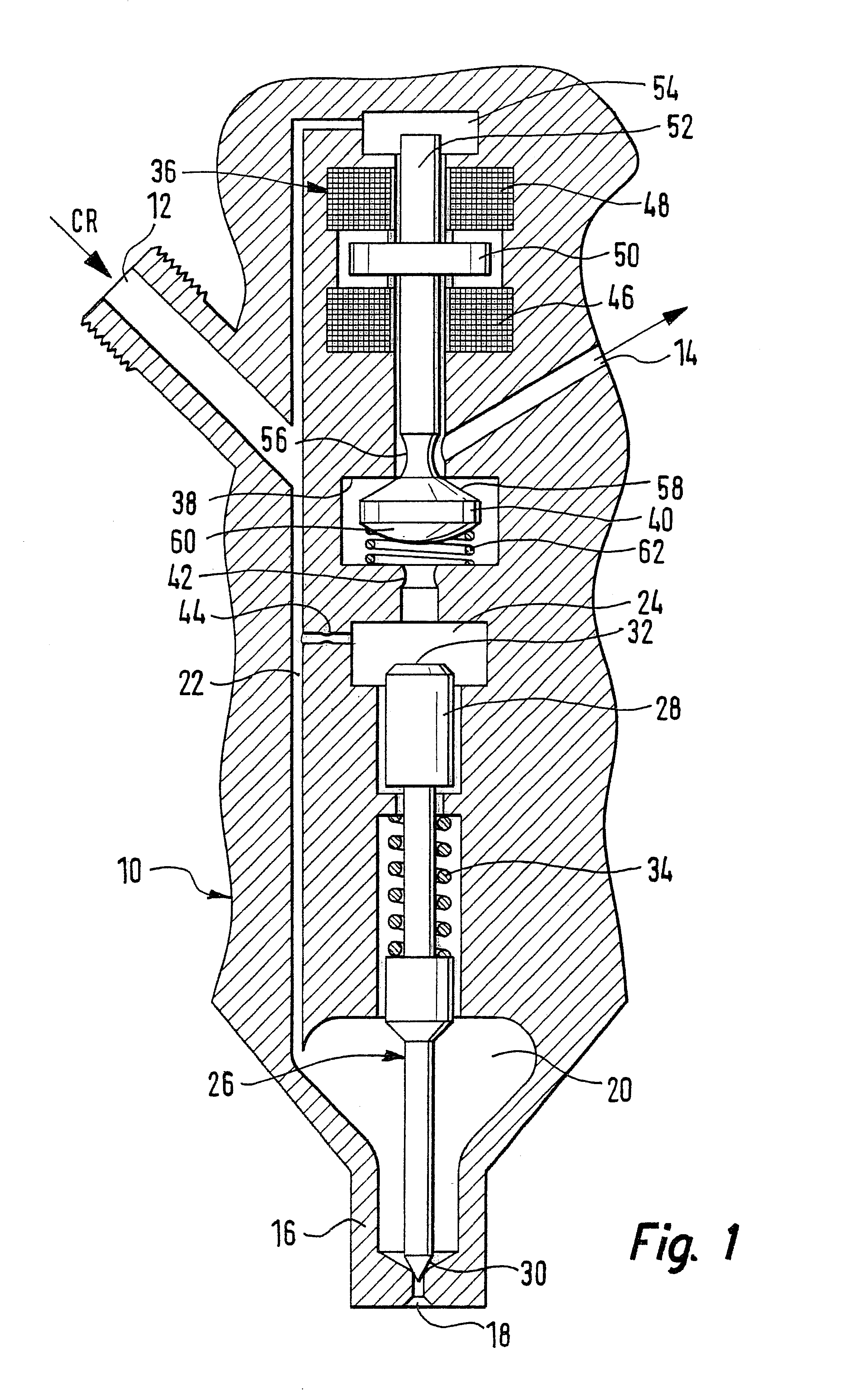
In FIG. 1, a magnet injector for the fuel reservoir injection system of a diesel engine is shown schematically in cross section. The injector has a housing 10, which communicates with the high-pressure reservoir (or common rail, not shown) of the reservoir injection system via a fuel inlet 12 and with the fuel tank (not shown) via a fuel outlet 14. The high-pressure reservoir communicates in turn via a high-pressure pump (not shown) with the fuel tank, which compresses the fuel in the reservoir to the system pressure, at which the injection is to take place.

On the lower end, the housing 10 has a nozzle 16 with a nozzle opening 18 and with a nozzle chamber 20 located above the nozzle opening. The nozzle chamber 20 communicates with the inlet 12 via a nozzle conduit 22 in the housing 10. The housing 10 furthermore has a longitudinal bore, which discharges at its lower end into the nozzle chamber 20 and at its upper end into a control chamber 24.

The injector furthermore has a nozzle ne...


PUM


Abstract

The invention relates to a magnet injector for fuel reservoir injection systems, having a fuel inlet and a fuel outlet, a control chamber, which communicates with the inlet, a nozzle which communicates with the inlet and a nozzle needle, which has a tip for closing the nozzle opening and has a shaft end that borders on the control chamber; and a magnet valve which has a first electromagnet, an armature, a valve chamber that communicates with the outlet via a first passage and with the control chamber via a second passage, and a throttle body which is located in the valve chamber and is connected to the armature, wherein the throttle body, in the state of repose of the injector, is kept in a first terminal position, in which it blocks one of the two passages, and is moved toward a second terminal position, in which it opens this passage, by triggering of the first magnet. To make shorter switching times possible, the magnet valve has a second electromagnet, which upon triggering acts on the armature oppositely from the first electromagnet. The throttle body is embodied such that in its second terminal position, it blocks the other of the two passages and along the way between its two terminal positions opens both passages.

Description

1. Field of the InventionThe invention relates to a magnet injector for fuel reservoir injection systems, having:a fuel inlet and a fuel outlet; a control chamber, which communicates with the inlet; a nozzle, which communicates with the inlet; and a nozzle needle, which has a tip for closing the nozzle opening and has a shaft end that borders on the control chamber; anda magnet valve, which has a first electromagnet, an armature, a valve chamber that communicates with the outlet via a first passage and with the control chamber via a second passage, and a throttle body which is located in the valve chamber and is connected to the armature,wherein the throttle body, in the state of repose of the injector, is kept in a first terminal position, in which it blocks one of the two passages, and is moved toward a second terminal position, in which it opens this passage, by triggering of the first magnet. To make shorter switching times possible, the magnet valve has a second electromagnet, ...

Claims


Application Information

Patent Timeline
IPC IPC(8): F02M59/46F02M59/00F02M45/08F02M45/00F02M47/02F02M47/00F02M51/06F02M61/10
CPCF02M45/08F02M47/027F02M63/0019F02M63/0035F02M63/0043F02M63/0056F02M63/0073F02M63/0033
Inventor MATTES, PATRICK
Owner ROBERT BOSCH GMBH
Why Eureka
Try Eureka