Parallel divided flow-type fluid supply apparatus, and fluid-switchable pressure-type flow control method and fluid-switchable pressure-type flow control system for the same fluid supply apparatus

a flow-type fluid supply and flow-type technology, applied in fluid pressure control, process and machine control, instruments, etc., can solve the problems of small transient effect on upstream pressure po, unpredictable problems, and semiconductor semiconductor defects

Inactive Publication Date: 2002-07-23
FUJIKIN INC +2
View PDF3 Cites 59 Cited by
  • Summary
  • Abstract
  • Description
  • Claims
  • Application Information

AI Technical Summary

Problems solved by technology

But a problem is encountered with an arrangement in which material gas G is supplied through one regulator and branched off into two or more flow passages. FIG. 15 shows an arrangement in which the flow of the material gas G from one regulator RG branches off to two flow passages S.sub.1 and S.sub.2.
In the process of manufacturing semiconductors, this problem could cause lattice defects in the semiconductor.
This change could lead to unpredictable problems through "chaos phenomena."
However, little transient effect is wrought on upstream pressure Po.
However, the pressure changing device is itself expensive.
That would make the whole of the fluid supply arrangement complicated and large, sending up the costs.
The problem is that each mass flow controller has its linearity corrected for a specific kind of gas and a specific low rate range.
That is, the mass flow controller cannot be used for other than the kind of gas for which the controller is adjusted.
The mass flow controller is expensive and so are replacement parts.
That increases the costs of gas supply facilities and the running costs.
Furthermore, if the mass flow controller is not replaced for a new kind of gas and, instead, the linearity is corrected every time a new gas is used, it takes long and it could happen that the operation of the manufacturing plant has to be temporarily suspended.
This transient change in turn has an affect on the process in the reaction chamber off the branch line, causing a number of problems.
If each branch line is provided with one regulator to avoid such transient changes, meanwhile, that will make the fluid supply arrangement complicated and bulky, boosting the costs.
Furthermore, a large number of expensive standby mass flow controllers have to be stocked.
That increases the costs of gas supply facilities and the running costs.
As a result, the inventors concluded that the mass flow controller cannot absorb the transient effect very well because the controller measures the flow rate on the basis of the amount of heat transfer or heat carried by the fluid, and if the change in flow rate is higher than the flow velocity, the control of the flow rate cannot follow the change in flow rate well.

Method used


Image

  • Parallel divided flow-type fluid supply apparatus, and fluid-switchable pressure-type flow control method and fluid-switchable pressure-type flow control system for the same fluid supply apparatus
  • Parallel divided flow-type fluid supply apparatus, and fluid-switchable pressure-type flow control method and fluid-switchable pressure-type flow control system for the same fluid supply apparatus
  • Parallel divided flow-type fluid supply apparatus, and fluid-switchable pressure-type flow control method and fluid-switchable pressure-type flow control system for the same fluid supply apparatus

Examples


example 2

Pressure Type Flow Controller

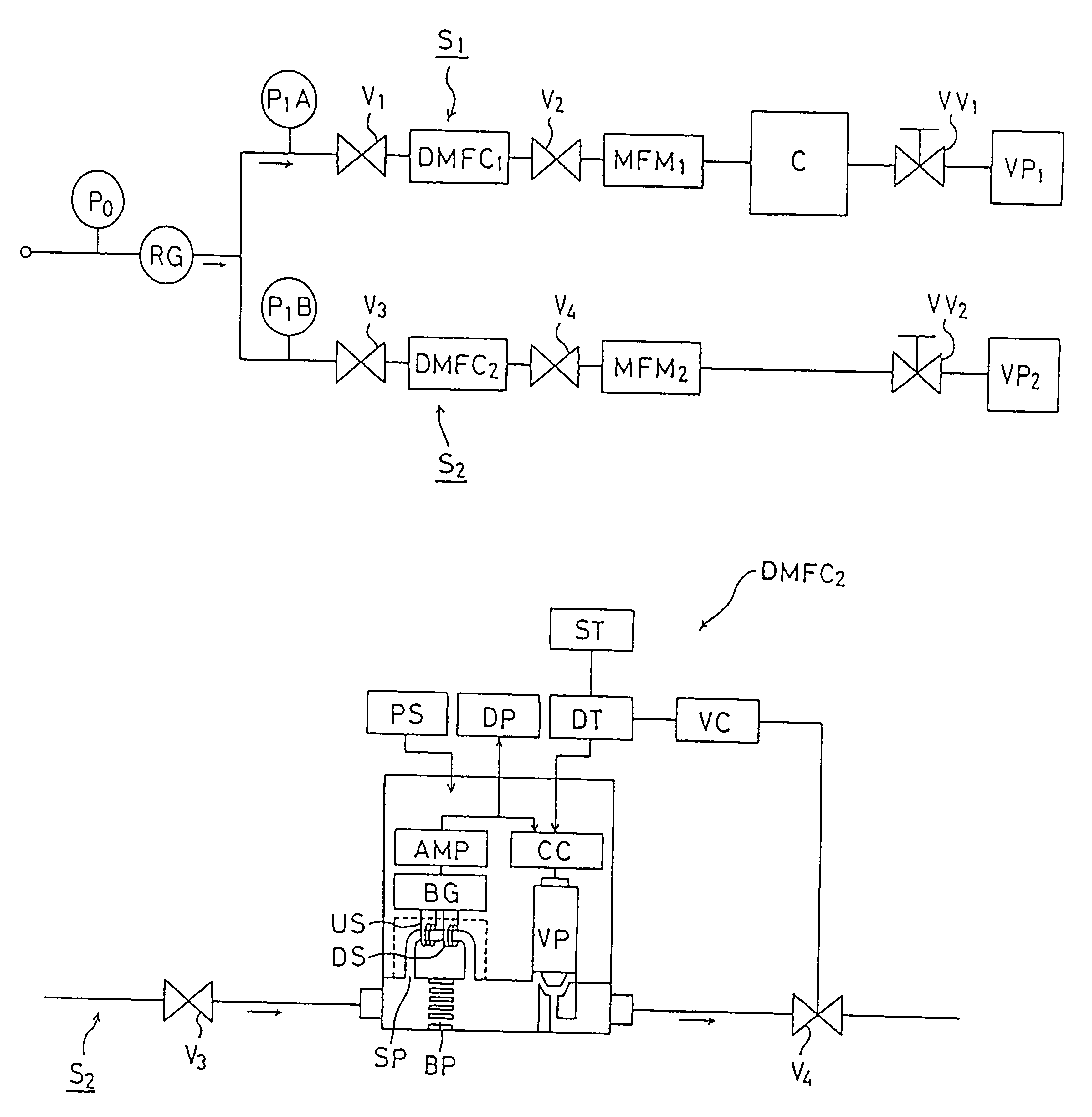
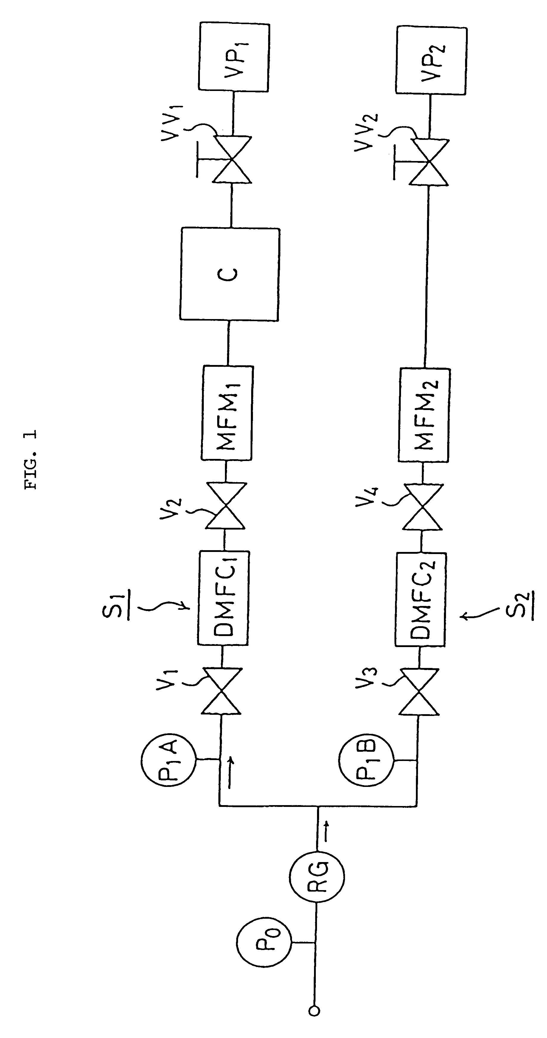
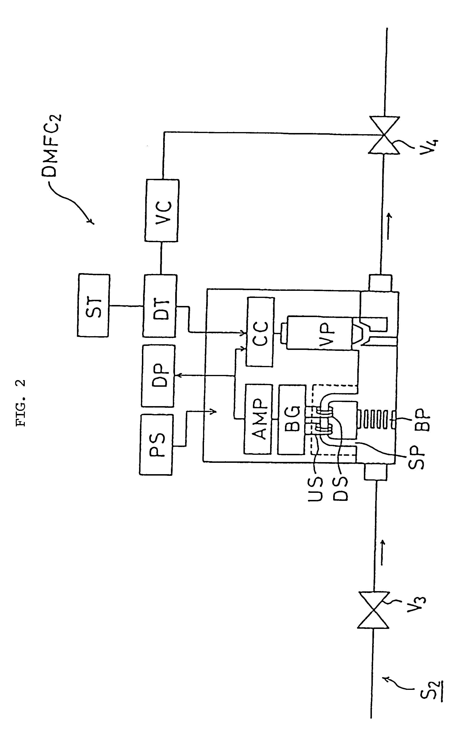
FIG. 7 is a schematic diagram of an embodiment of the parallel divided flow type fluid supply apparatus according to a further embodiment of the present invention in which pressure-type flow control systems are used. FIG. 7 is identical with FIG. 1 in arrangement except that pressure-type flow control systems FCS.sub.1, FCS.sub.2 are used in place of time delay type mass flow controllers DMFC.sub.1, DMFC.sub.2. No description of like components will be repeated.

FIG. 8 is a schematic diagram of the pressure-type flow control system FCS.sub.1 in flow passage S.sub.1. The same is provided in flow passage S.sub.2. Referring to FIG. 8, OR indicates orifice; P.sub.1, pressure gauge on the upstream side of the orifice; AP.sub.1, amplifier; A / D, A-D converter; M, temperature compensator; SS, flow rate setter; CC, comparison circuit; AP.sub.2, amplifier; DV, drive; and CV, control valve. It is also understood that SS, CC, M and AP.sub.2 as a whole are called calc...

example 3

Application Example of Fluid Switchable Pressure-type Flow Control System

FIG. 10 shows an application example of the fluid switchable pressure-type flow control system according to a still further embodiment of the present invention. This corresponds to the prior art using mass flow controllers shown in FIG. 18. The fluid switchable pressure-type flow control system is indicated by FCS.sub.2a. That is, the flow rates of three kinds of gases--H.sub.2 gas, O.sub.2 gas and N.sub.2 gas--are controlled by two pressure-type flow control systems FCS.sub.1 and FCS.sub.2a.

In FIG. 10, two pressure-type flow control systems FCS.sub.1 and FCS.sub.2a are required to supply H.sub.2 and O.sub.2 simultaneously to the reactor RR. But O.sub.2 and N.sub.2 do not have to be fed to the reactor RR at the same time, and the fluid switchable pressure-type flow control system FCS.sub.2a can be used for control of the flow rates of both O.sub.2 and N.sub.2.

To generate moisture, the first step is to open valv...

example 4

Another Application Example of Fluid Switchable Pressure-type Flow Control System

FIG. 11 shows another application example of the fluid switchable pressure-type flow control system FCS.sub.2a --an example where the fluid switchable pressure-type flow control system FCS.sub.2a is applied to the so-called single chamber multiple process in semiconductor manufacturing facilities.

If Si is going to be nitrided immediately after oxidation in FIG. 11, for example, the system is first purged with N.sub.2 gas and then H.sub.2 gas and O.sub.2 gas are supplied to the reactor RR to oxidize Si. Then, N.sub.2 O gas is supplied to nitride the Si oxide film. Finally, N.sub.2 gas is supplied to purge the system.

That is why the application example of the flow control system in FIG. 11 uses one pressure-type flow control system FCS.sub.1 and one fluid switchable pressure-type flow control system FCS.sub.2a --a total of two units. But if this fluid supply apparatus is formed of the prior art mass flow ...


PUM


Abstract

A fluid supply apparatus with a plurality of flow lines branching out from one pressure regulator with the flow lines arranged in parallel and constructed so that opening or closing one flow passage will have no transient effect on the steady flow of the other flow passages. Each flow passage is provided with a time delay-type mass flow controller MFC so that when one closed fluid passage is opened, the mass flow controller on that flow passage reaches a set flow rate Qs in a specific delay time DELTAt from the starting point.The invention includes a method and an apparatus in which a plurality of gas types can be controlled in flow rate with high precision by one pressure-type flow control system.

Description

1. Field of the InventionThe present invention relates to an apparatus for supplying gases or the like for use in the production of semiconductors, chemicals, precision machine parts, etc. More specifically, this invention relates to a parallel divided flow type fluid supply apparatus so configured that when any one of a plurality of flow passages arranged in parallel is opened for fluid to flow, the effect of that operation on the flow rates in other flow passages is minimized.The present invention also relates to a method of controlling the flow rates of various gases used in an apparatus for supplying gases or the like for use in the production of semiconductors, chemicals, precision machine parts, etc. More specifically, this invention relates to a fluid switchable pressure-type flow control method and a fluid switchable pressure-type flow control system (FCS) in which the flow of various gases can be regulated with high precision by one pressure-type flow control system on the ...

Claims


Application Information

Patent Timeline
Patent Type & Authority Patents(United States)
IPC IPC(8): G05D7/06
CPCG05D7/0658G05D7/0664Y10S438/935Y10T137/86389Y10T137/0396Y10T137/87877Y10T137/87917Y10T137/7761Y10T137/7759G05D7/06
Inventor OHMI, TADAHIROKAGATSUME, SATOSHISUGIYAMA, KAZUHIKOMINAMI, YUKIONISHINO, KOUJIDOHI, RYOUSUKEYONEHANA, KATSUNORIIKEDA, NOBUKAZUYAMAJI, MICHIOHIROSE, JUNFUKAZAWA, KAZUOKOIZUMI, HIROSHINAGAOKA, HIDEKIMORIMOTO, AKIHIROUNO, TOMIOIDETA, EIJIMATSUMOTO, ATSUSHIUENOYAMA, TOYOMIHIROSE, TAKASHI
Owner FUJIKIN INC
Why Eureka
Try Eureka