Method and apparatus for detecting refractive defects in transparent containers

a technology for refractive defects and transparent containers, applied in the direction of instruments, specific gravity measurement, counting objects on conveyors, etc., can solve the problems of requiring substantial maintenance, limiting the inspection speed, and requiring additional maintenance, so as to achieve efficient and rapid inspection of transparent containers

Inactive Publication Date: 2002-07-23
AGR INT
View PDF7 Cites 58 Cited by
  • Summary
  • Abstract
  • Description
  • Claims
  • Application Information

AI Technical Summary

Benefits of technology

The apparatus of the present invention provides a diffuse light source, a grid filter which preferably has a plurality of alternating light and dark bands which provide intensity gradients throughout the field of view with a lens directing the grid filtered light through the transparent container wall of the container being inspected. The light passing through container walls which do not have a refractive defect either of a structural or objectionable cosmetic variety will provide predetermined light impinging on the detector which in turn converts the light into corresponding electrical signals. The processor which may be any suitably programmed computer having stored information regarding the nature of defects which will result in rejection of the container, and preferably the irregularities in the container wall which are deemed acceptable, will effect a comparison between the electrical signals and the information and make a determination as to whether...

Problems solved by technology

The nature of this system, however, imposes a meaningful limitation on speed of inspection, enhances only horizontal edges of the container and provides a system which would require substantial maintenance.
Such rotation limits inspection speed as well as requiring additional maintenance.
These are large horizontal defects that are structurally hazardous.
These systems are designed primarily to enhance gross defects such as ribbon tears and the like which compromise the strength of the container, but are not designed to also detect cosmetic defects in the container.
The gradient produced by the solid black to solid white strip...

Method used


Image

  • Method and apparatus for detecting refractive defects in transparent containers
  • Method and apparatus for detecting refractive defects in transparent containers
  • Method and apparatus for detecting refractive defects in transparent containers

Examples


Embodiment Construction

As employed herein, the term "refractive defect" means a defect in a transparent container wall which includes a defect of a predetermined magnitude resulting from either (a) a variation in the thickness of the container wall in a particular region or (b) a variation in refractive index in a particular portion of the container wall and shall expressly exclude desired irregularities, such as mold seams, support rings, finishes, lettering, decorative or informational irregularities, and desired thickness changes.

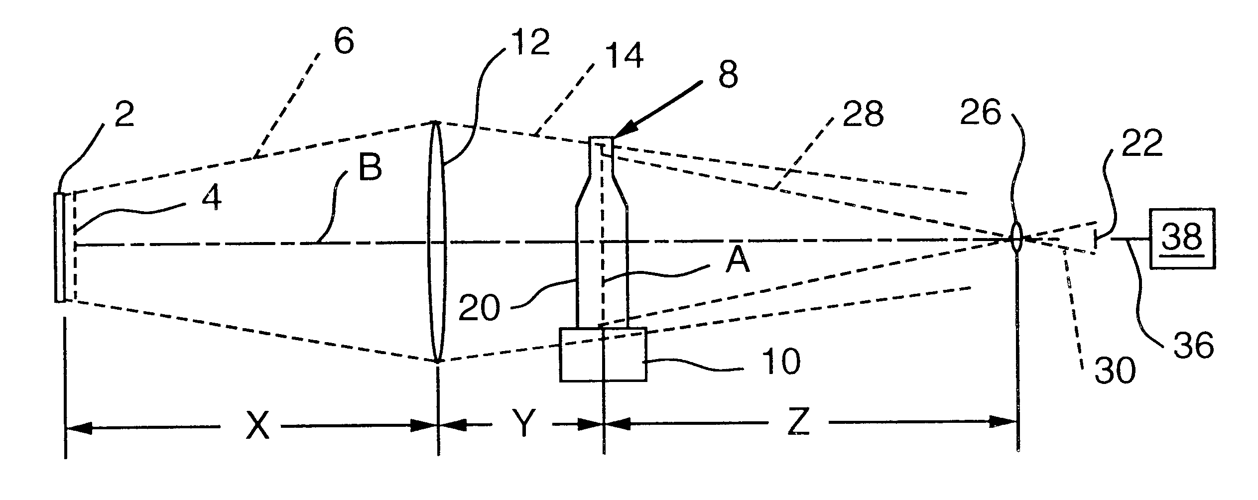
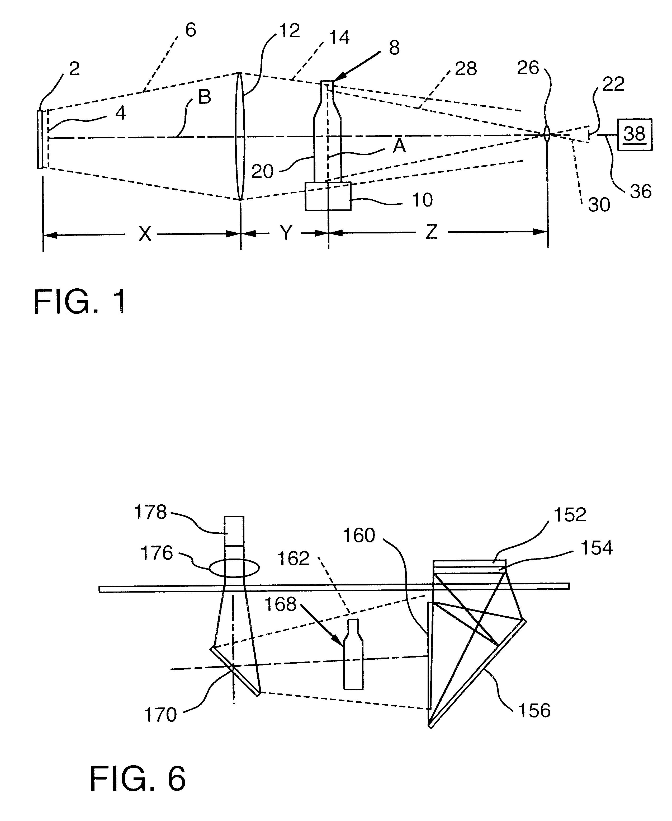
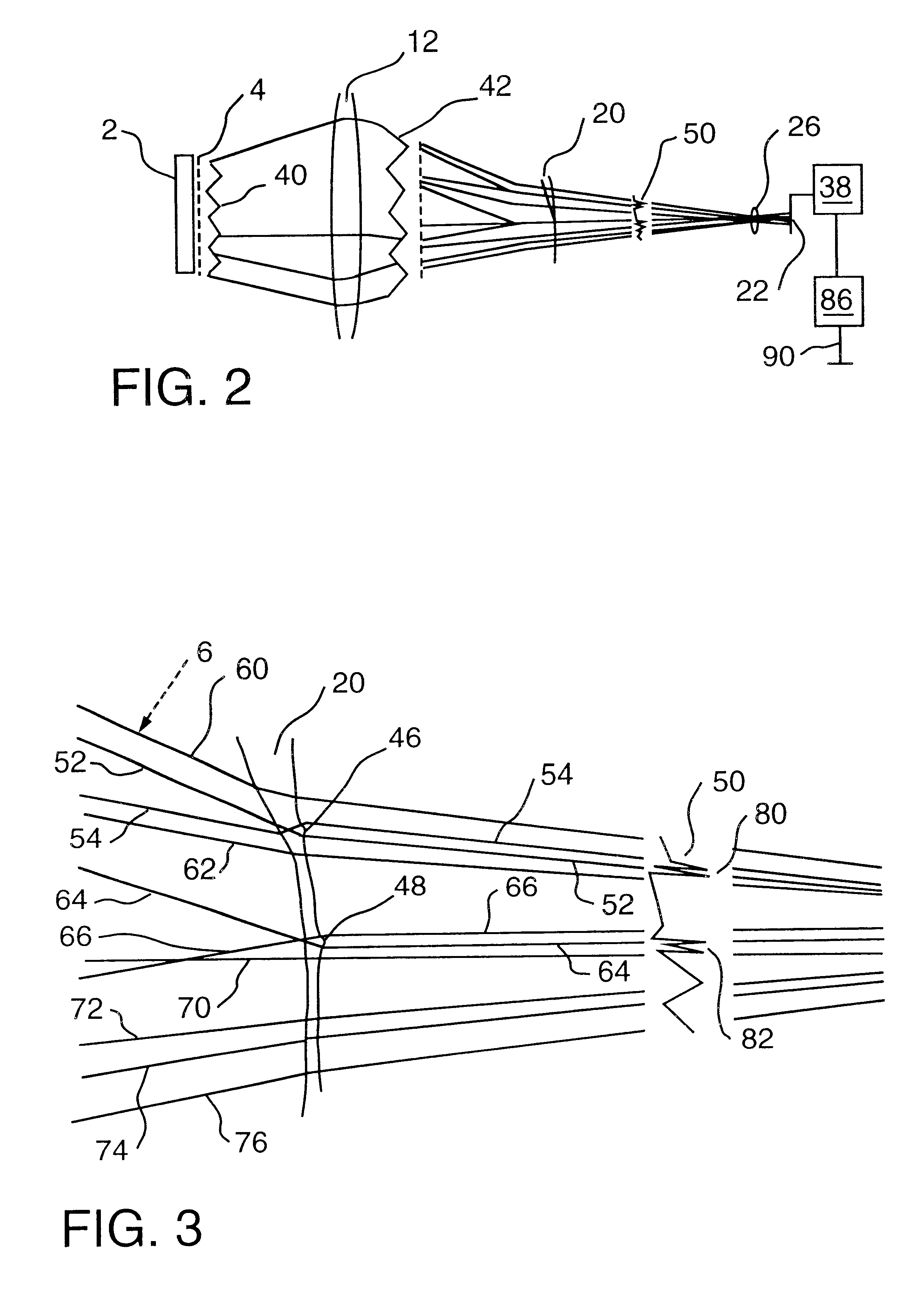
Referring now in greater detail to FIG. 1, there is shown a light source 2 which is structured to emit diffused light which passes through grid filter 4. A glass container 8 to be inspected is positioned at a container inspection station 10 which may be a continuous conveyor, a stationary support, or any other suitable structure. In order to enhance the efficiency of light transmission of the multiple intensity gradient beam 6 emerging from the grid filter 4, the diverging lig...


PUM


Abstract

A method of inspecting a transparent container for refractive defects includes positioning a light source in spaced relationship with respect to a detector which is operatively associated with a processor for receiving electrical signals from the detectors responsive to light passing through the container being received by the detector. The method includes positioning a grid filter having a plurality of alternating dark and light bands adjacent the light source so as to provide a multiple intensity gradient to the container. The container is positioned between the light source and the detector with the grid filter serving to provide adjacent alternate light and dark bands of light impinging on the container. Refractive defects will cause a distortion of the intensity gradient which will be received by the detector. In a preferred embodiment, a plurality of light and dark bands are generally horizontally oriented and produces a generally triangular wave having a constant absolute slope. A processor is employed to receive the electrical signals emitted by the detector responsive to the light impinging thereon and make a determination as to whether refractive defects exist while ignoring desired irregularities in the container. Corresponding apparatus which employs alternating light and dark bands in the grid filter and in the preferred embodiment employs dark bands of single intensity gradient and light bands of single intensity gradient. Each band has a constant gradient of light intensity passing therethrough. The grid filters produces a triangular wave having a constant absolute slope.

Description

BACKGROUND OF THE INVENTION1. Field of the InventionThe present invention provides a method for inspecting transparent containers for refractive defects and associated apparatus. More specifically, the invention provide:s for a multiple intensity gradient light grid filter which converts light emitted by a diffuse light beam into a light gradient which impinges upon a transparent container with a detector receiving light passing through the container and emitting responsive electrical signals to a processor which determines whether a refractive defect exists in the container.2. Description of the Prior ArtIt has long been known to inspect various properties of transparent containers by passing a light beam through the container and having detectors receive the light passing therethrough, convert the light into corresponding electrical signals and deliver the signal to a suitably programmed processor which compares the received signal with a stored standard in order to determine a gi...

Claims


Application Information

Patent Timeline
IPC IPC(8): G01N21/90G01N21/958G01N21/88
CPCG01N21/90G01N21/9036G01N2021/8832
Inventor WEILAND, JOSEPH G.FISHER, EDWARD J.
Owner AGR INT
Why Eureka
Try Eureka