Enhanced minimum tillage planter/renovator system

a planter/renovator and minimum tillage technology, applied in the field of minimal tillage planter/renovator system, can solve the problems of disturbing the renovation/planting process, requiring a lot of weight for cutting coulters, and providing an inefficient and sometimes difficult means of establishing leading slices, etc., to achieve convenient operation, enhance the seed bed and clean furrow, and reduce the effect of labor intensity

Inactive Publication Date: 2002-07-30
TARVER III SAM A
View PDF4 Cites 40 Cited by
  • Summary
  • Abstract
  • Description
  • Claims
  • Application Information

AI Technical Summary

Benefits of technology

Unlike the prior art, the present invention contemplates a minimum tillage planter/renovator system which provides an enhanced seed bed and clean furrow, with nominal ground cover disturbance, in a variety of soil conditions. Thus,

Problems solved by technology

However, when conventional minimum tillage planters are utilized with soft or spongy ground, which may have a lot of humus, for example, the furrow and seedbed is formed, only to have it shrink or disappear, with the furrow providing little open area on the ground cover sunlight and passage of the seedlings therethrough.
A general problem with this prior art arrangement is that the leading slicing coulter requires far too much weight to penetrate hard ground, providing an inefficient and sometimes difficult means of establishing a leading slice.
Further, in soft or spongy soil conditions, the coulter may not cut trash in its path, instead burying the trash beneath the coulter, and into the path of the ripping point and/or into the seedbed, disturbing the renovation/planting process.
The co

Method used


Image

  • Enhanced minimum tillage planter/renovator system
  • Enhanced minimum tillage planter/renovator system
  • Enhanced minimum tillage planter/renovator system

Examples


first embodiment

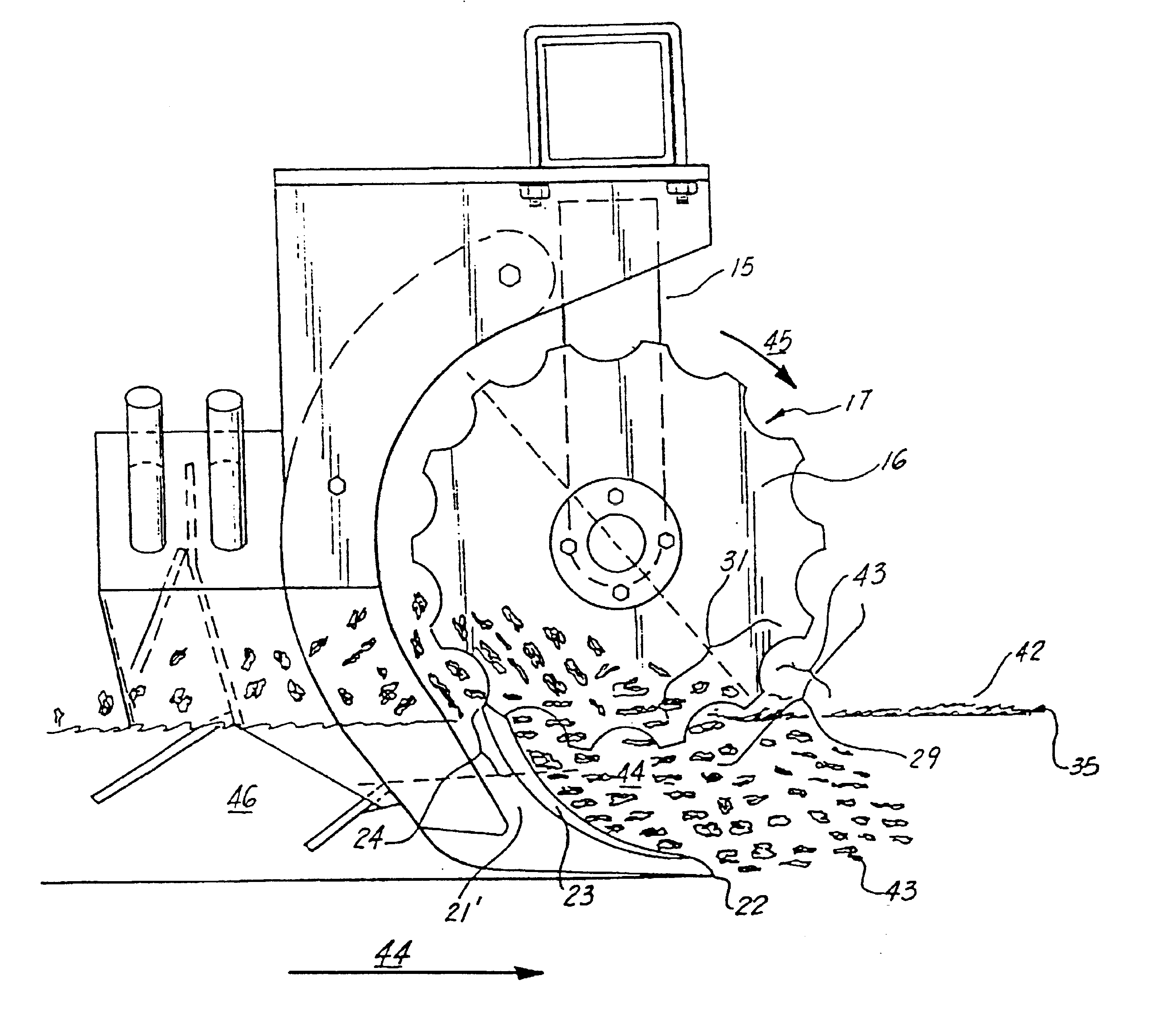
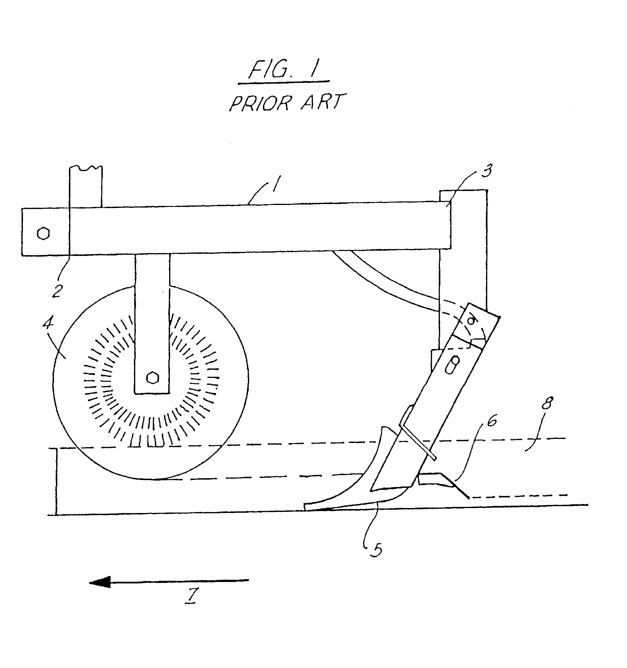
Referring to FIGS. 3A-3C of the drawings, the present invention teaches a minimum tillage planter / renovator which dispenses with the necessity of a leading slicing coulter (4 in FIG. 1), providing an enhanced seedbed with a lighter implement.

As shown, the minimum tillage planter / renovator 10 comprises a frame 11 having a first, frontal end 12 and a second, rear end 13. Shown atop the frame is a standard, three point hitch 14, which may be utilized by a tractor or other implement to motivate the present system.

Continuing with the drawings, emanating from the frame 11 near the first end 12 in general vertical fashion is a front vertical support member 15, configured to support first 16 and second 17 coulter discs about said vertical support member, via axle 18 in angled relationship, as will be further discussed infra. As shown, the outer diameter 19 of the coulter discs 16, 17 may be rippled 20, scalloped, or otherwise shaped to form a cutting edge which supports a grinding action, a...

second embodiment

Preferred, Second Embodiment of the Present Invention

Utilizing a planter / renovator P having a frame, first and second coulters, and a foot shank / ripping point identical to the planter / renovator of FIGS. 5A-5F, unless otherwise indicated (the discussion of said planter / renovator is hereby incorporated by reference), continuing with FIG. 6, a second preferred embodiment of the present invention includes the planter / renovator of FIGS. 5A-5F, including the rippled coulters, frame, foot shank / ripping point, and fertilizer / seed dispensing system associated with first and second mole plows configured and as discussed supra, with the additional feature of furrow trimming means for trimming the edges of the furrow formed by the minimum tillage planter / renovator P, further enhancing the appearance and uniformity of the furrow. As shown, the frame F comprises a front section 500 and a rear section 501 which is pivotally connected 502, and which is held in a generally aligned fashion via shear ...

embodiment 8

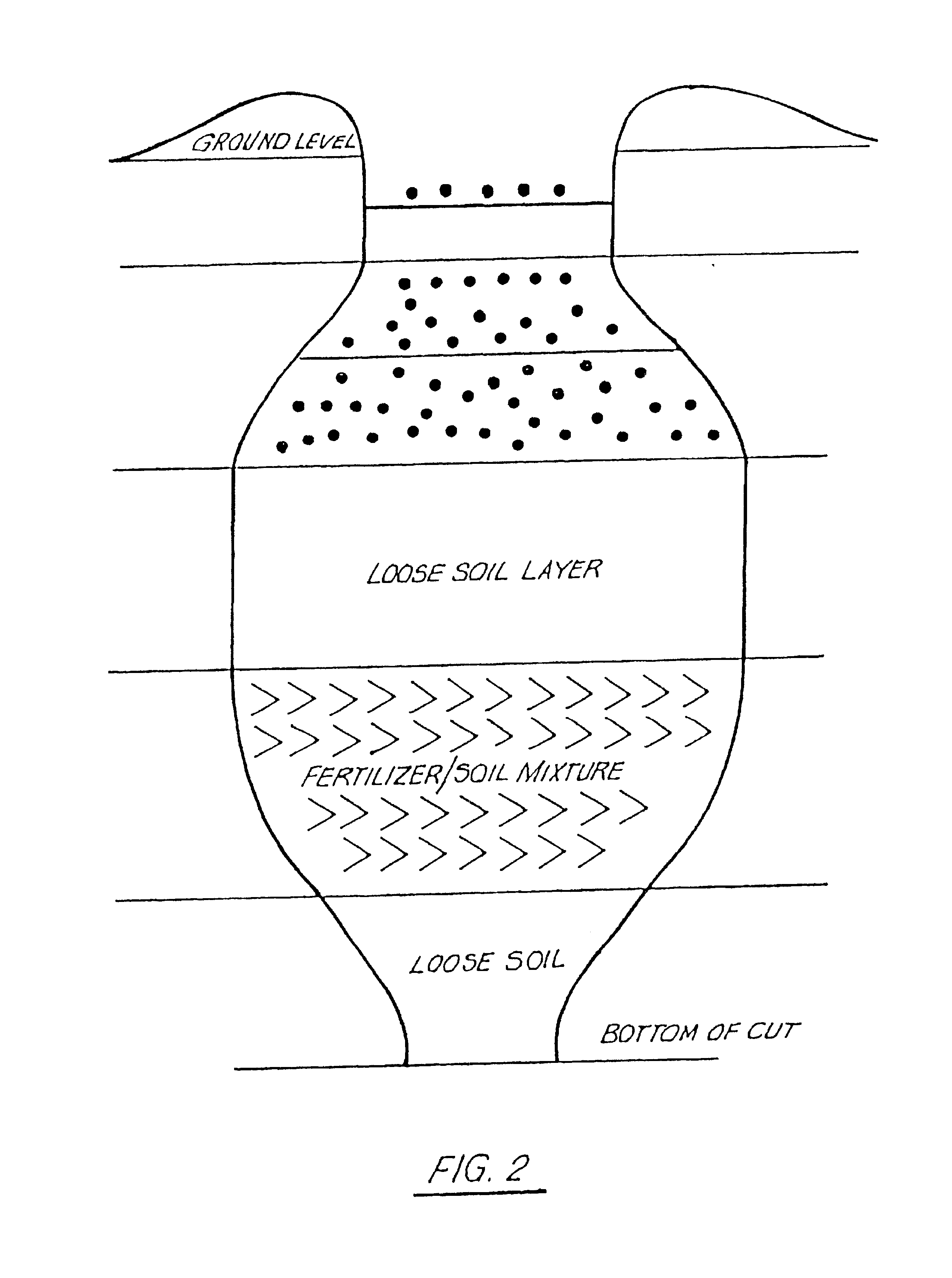
The primary benefit of staggering the implements is that, in use, the ground cover between the rows, which may be spaced 13-15" inches apart via the spacing of the implements, is undisturbed on the surface, but below the surface, the sod / soil is fractured by the staggering of the implements, including primarily the ripping point of each implement, by the amount indicated above (preferred embodiment 8"). Accordingly, water, fertilizer, nutrients to feed the entire ground area are more readily distributed, while simultaneously facilitating more even distribution of water, fertilizer nutrients from one furrow to the next, renovating the soil, and feeding all of the root system of any plants in the furrows. A tractor pulling the main frame would then prepare as many furrows as there are implements provided upon the main frame.


PUM


Abstract

A planter/fertilizer wherein there is provided a ripping point configured to penetrate a predetermined depth into the soil or sod, the ripping point designed to facilitate a splitting and lifting of the soil, forming a seed bed void, while cutting any organic ground cover, which might comprise, for example, sod, widening the ground cover, and lifting same to a prominent head, wherein first and second coulters, situated above and about the ripping point, are configured to independently engage and cut first and second sides of the lifted ground cover, trash and the like, respectively, then cutting the lifted ground cover, etc., as the coulters rotate, the coulters cooperatively grinding at least a portion of the lifted ground cover, forming tilth, and redepositing the tilth into the seedbed void, providing an enhanced seedbed region with nominal surface disturbance, and a clean furrow. Situated behind the first and second mole plows and fertilizer and seed chutes are opposing first and second wheels, the first wheel a larger diameter furrow trimming wheel, having outwardly emanating therefrom a depth ring or drum for controlling the depth and covering of the seed for the first side of the furrow, the second wheel being smaller in diameter than the first and situated to trim the furrow and assist further in covering the seed for the second side of the furrow, the first and second wheels having different diameters so that they cooperatively rotate at different speeds to prevent clogging, and are situated at opposing angles on horizontal and vertical planes so as to be self cleaning in a variety of soil conditions. Following the first and second wheels is a pressure wheel about the width of the furrow, which is directed over the furrow so as to apply pressure to the furrow, flattening so as to complete the furrow forming process.

Description

This invention relates to a cultivation equipment and methods, and in particular to a minimum tillage planting / renovation system configured to facilitate an enhanced seedbed in a variety of soil conditions, while maintaining nominal surface disturbance. The present invention may further be configured, for example, to provide intercrop planting, renovating, and / or fertilizing.The system of the present invention contemplates a planter / fertilizer wherein there is provided a ripping point configured to penetrate a predetermined depth into the soil or sod, the ripping point designed to facilitate a splitting and lifting of the soil, forming a seed bed void, while cutting any organic ground cover, which might comprise, for example, sod, widening the ground cover, and lifting same to a prominent head, wherein first and second coulters, situated above and about said ripping point, are configured to independently engage and cut first and second sides of the lifted ground cover, trash and the...

Claims


Application Information

Patent Timeline
IPC IPC(8): A01B13/08A01B13/00A01B49/00A01B49/02A01B49/06A01C5/00A01C21/00A01C7/00A01C5/06
CPCA01B49/027A01B49/06A01C5/062A01C7/006A01C21/002A01B13/08Y02A40/22Y02P60/20
Inventor TARVER, III, SAM A.
Owner TARVER III SAM A
Why Eureka
Try Eureka