Power window controlling device

a technology of controlling device and window glass, which is applied in the direction of program control, dynamo-electric converter control, instruments, etc., can solve the problems of rotating speed and actuating the window glass in the reverse direction

a technology of controlling device and window glass, which is applied in the direction of program control, dynamo-electric converter control, instruments, etc., can solve the problems of rotating speed and actuating the window glass in the reverse direction

US6426604B1Inactive Publication Date: 2002-07-30MITSUBA CORP

Image

  • Power window controlling device
  • Power window controlling device
  • Power window controlling device

Examples


second embodiment

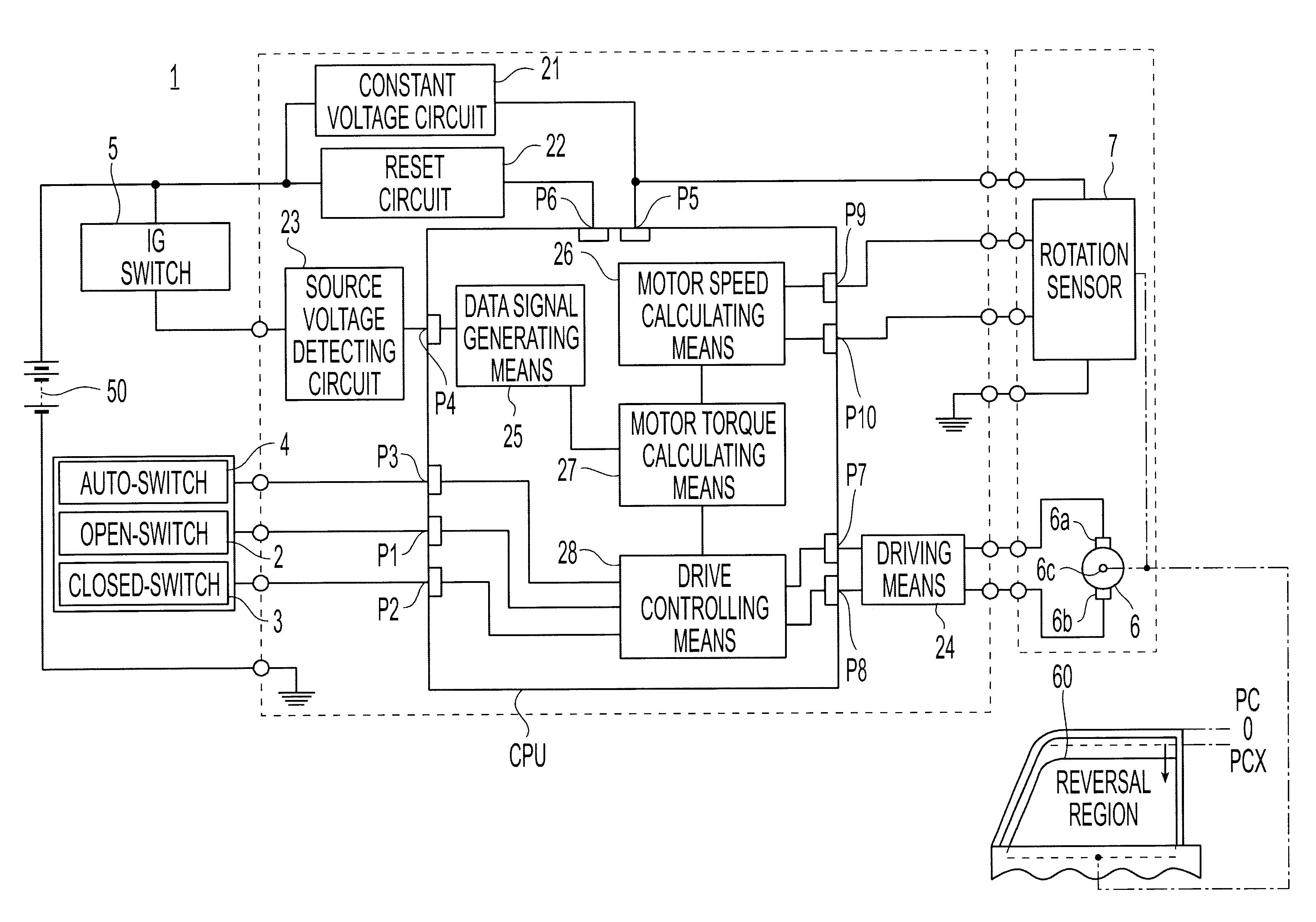
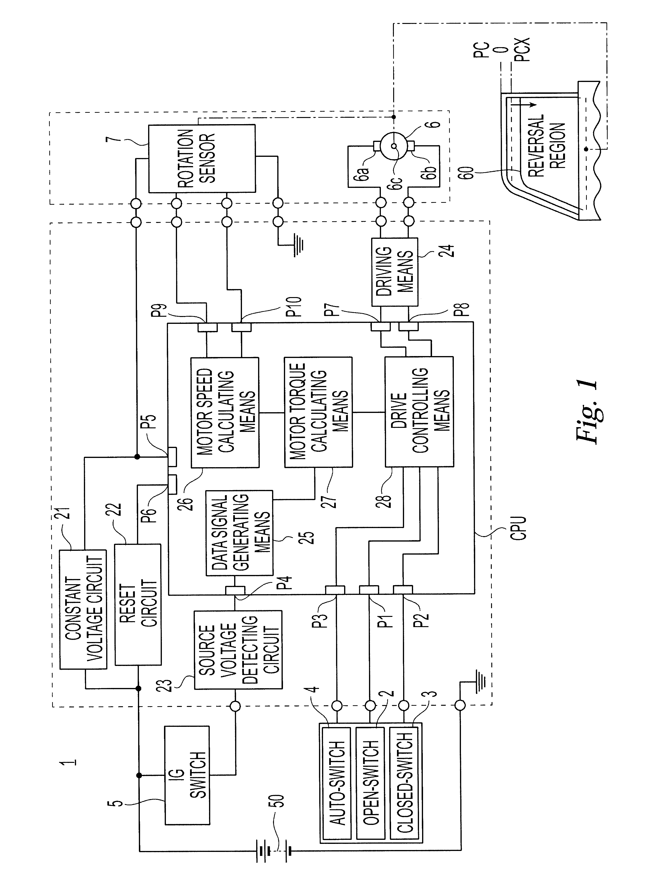
The second embodiment is shown in FIG. 15 of the power window controlling device according to this invention.

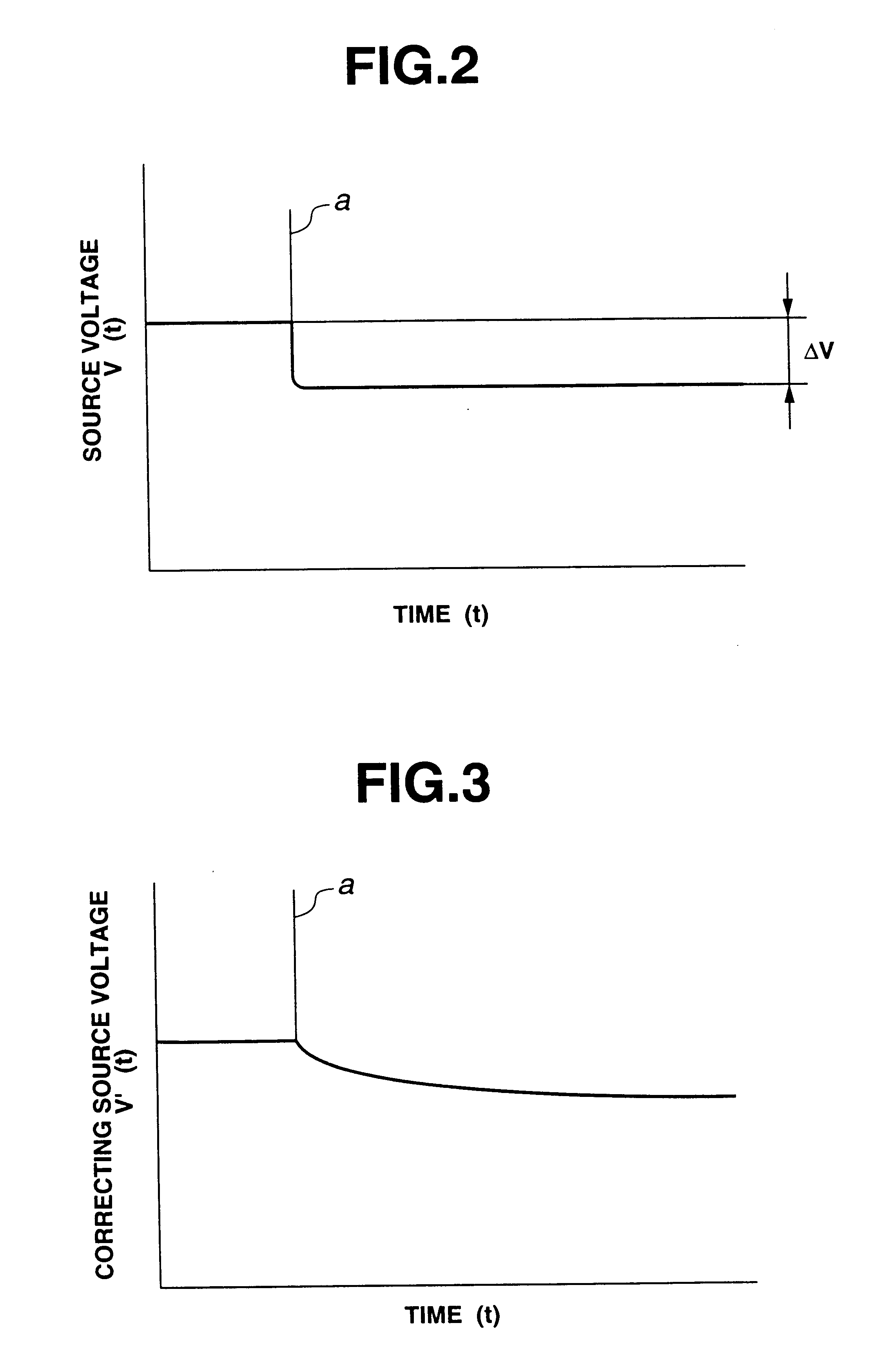
In the power window controlling device 1 in this example, the source voltage detecting circuit 23 is composed of a voltage correcting part 23a consisting of a resistor R1 and a capacitor C1, and a source voltage detecting part 23b consisting of a resistors R2 and R3. The time constant of the voltage correcting part 23a consisting of the resistor R1 and the capacitor C1 is set so as to be nearly equal to the time constant of the rotational speed of the electric motor 6.

When the ignition switch 5 is switched on, a voltage signal of the power source 50 integrated by the voltage correcting part 23a is given to the source voltage detecting part 23b, and the motor torque calculating means 27 is given with the voltage signal corresponding to the variation of the power source 50 by the source voltage detecting part 23b. Also in this case, the control action is carried out similarly t...


PUM


Abstract

A power window controlling device, which detects an obstruction-caught state without misunderstanding even if the electric potential at the power source drops abruptly, which comprises switches, an electric motor, a drive system, a drive controller, a rotation sensor, a motor speed calculating device, a source voltage detecting circuit, a data signal generating device and a motor torque calculator. The motor torque calculator calculates correcting data of motor torque on basis of a correcting data signal given from the data signal generating device and a rotational speed signal of the motor given from the motor speed calculator, and compares the correcting data of the motor torque with the predetermined criterion value in a case where the electric potential of the power source changes.

Description

1. Field of the InventionThis invention relates to a power window controlling device for driving a window glass of motor vehicles and, more particularly to an improved device which is possible to reversely drive the window glass in the opening direction at the time when torque data of the driving motor of the window glass increases over the predetermined value while the window glass is traveling a predetermined distance in the closing direction. In the power window controlling device according to this invention, when the electric potential of the power source drops, the fall of potential is detected and the torque data of the electric motor is corrected according to the lowered electric potential.2. Description of the Prior ArtAs the power window controlling device for driving the window glass of the motor vehicle, a device is well known which has an electric motor of which armature shaft is operatively connected with the window glass through a window regulator. The armature shaft o...

Claims


Application Information

Patent Timeline
30 Jul 2002
Publication
US6426604B1
IPC
G05B19/4062; G05B19/406; H02H7/085; E05F15/00; H02H7/093; H02H7/08
CPC
G05B19/4062; E05F15/41; H02H7/0851; E05Y2400/554; E05Y2400/564; G05B2219/37624; H02H7/093; E05Y2900/55
Inventors
ITO, TAKESHI; KATO, MASARU