Fast temperature programmed gas chromatograph

a gas chromatograph and fast temperature technology, applied in the direction of dispersed particle separation, instruments, separation processes, etc., can solve the problems of application preclusion, application using these analyzers are not typically run near their limits, and are not necessarily optimized for maximum revenu

Inactive Publication Date: 2002-08-06
ABB AUTOMATION INC
View PDF6 Cites 21 Cited by
  • Summary
  • Abstract
  • Description
  • Claims
  • Application Information

AI Technical Summary

Problems solved by technology

In some cases, the slowness of the application precludes the use of an analyzer in the control loop, relegating the analyzer to be used in an advisory capacity to the control algorithm.
Therefore, the applications using these analyzers are not typically run near their limits, nor are they necessarily optimized for maximum revenue by the refiner or chemical producer.
The major problem associated with this type of column is difficulty in packing longer lengths (>10 feet).
These columns are normally packed in 1 / 16 inch stainless tubing and it is visually impossible to determine if there are empty spaces within the column.
Although numerous advances have been made relative to speed of analysis by manipulating the column types and parameters, there is a theoretical limit to what can be done to decrease time for the sample to reach equilibrium between the mobile and stationary phases.
Factors such as no backflush, no liquid inject, limited column / detector choices, and lack of temperature control have limited the use of this technology to speed up applications, although recently some of the limitations have been resolved.

Method used


Image

  • Fast temperature programmed gas chromatograph
  • Fast temperature programmed gas chromatograph
  • Fast temperature programmed gas chromatograph

Examples


Embodiment Construction

)

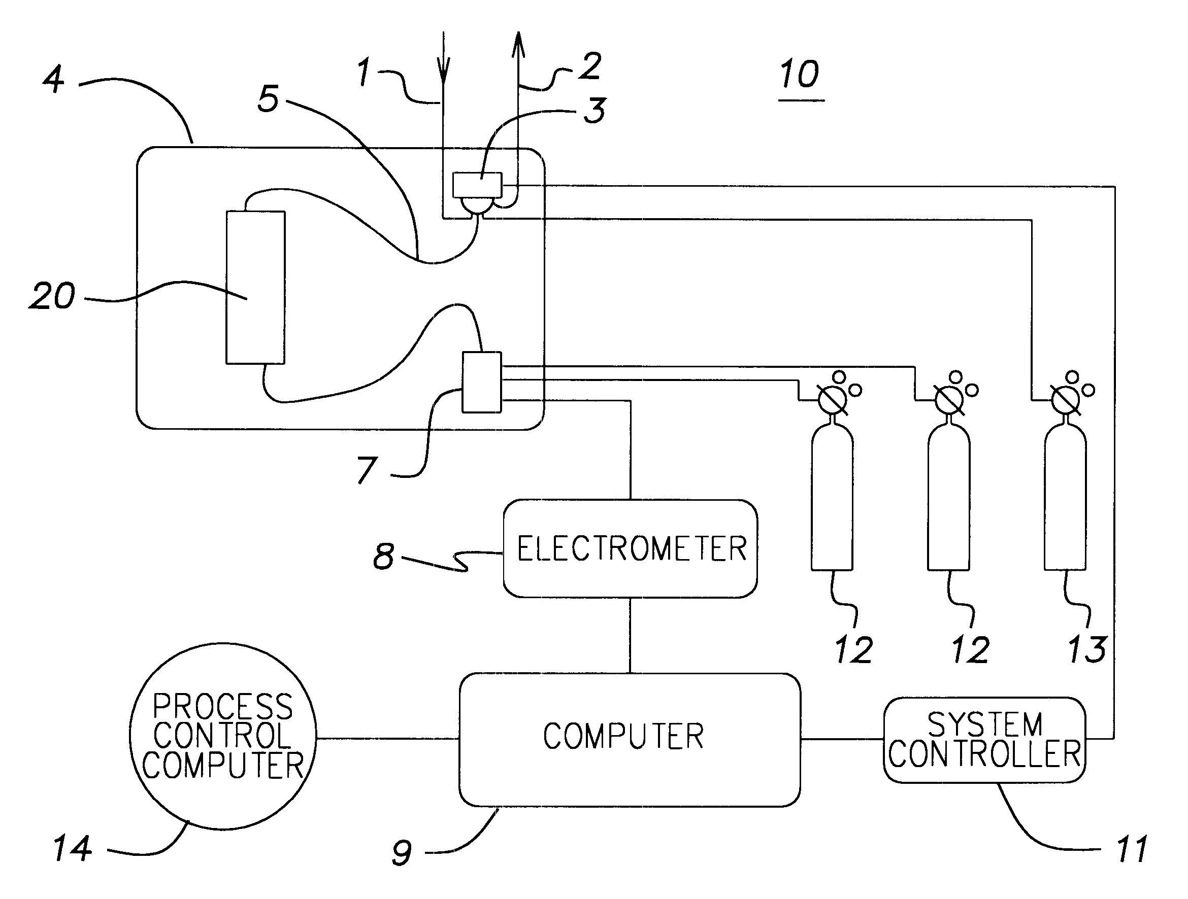
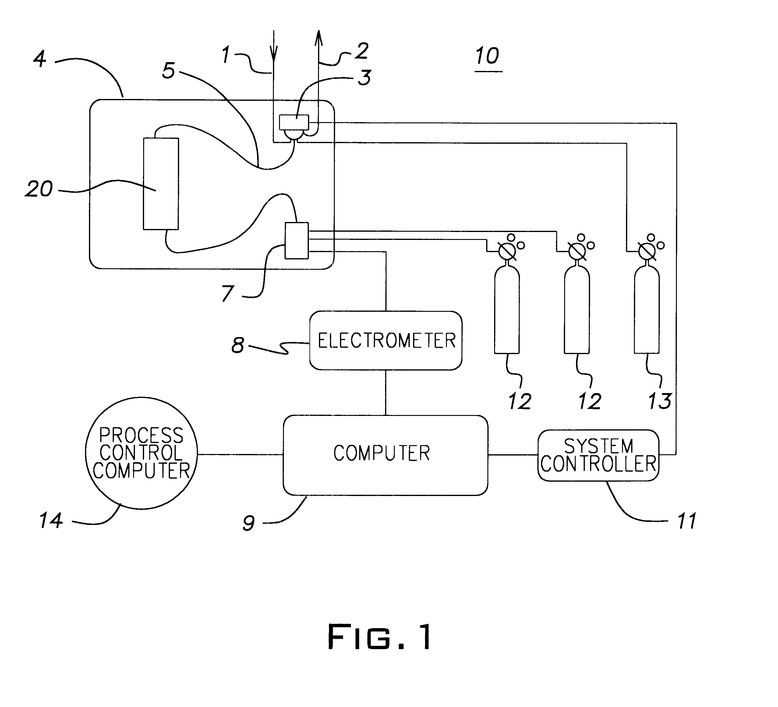
Referring now to FIG. 1, there is shown a functional block diagram representation of one embodiment for the GC 10 that includes the temperature programmed module 20 of the present invention. The sample enters the GC 10 through conduit 1, flows through the sample injector valve 3, and exits through a vent 2. The sample is injected into the micropacked column (shown in FIG. 2) that is part of the fast temperature programming module 20. The sample flows through the chromatographic column and into the flame ionization detector 7. The injection valve 3, the micropacked column of fast temperature programming module 20 and flame ionization detector 7 are contained in an enclosure 4 which in accordance with the present invention is not temperature controlled. Fuel gases, hydrogen and air 12, are supplied to the flame ionization detector 7 and carrier gas 13 is supplied to the injection valve 3 from sources outside of the enclosure 4.

The flame ionization detector 7 produces an electrical si...


PUM

PropertyMeasurementUnit
internal diameteraaaaaaaaaa
lengthsaaaaaaaaaa
flow rateaaaaaaaaaa

Abstract

A temperature programmed module for use in a gas chromatograph. The module has micropacked column and inner and outer jacket tubes. The inner jacket tube surrounds the column to provide a space between the that tube and the column. The outer jacket tube surrounds the inner jacket tube to provide a space between the two jacket tubes. Air which has a controlled temperature flows only in the space between the two jacket tubes when it is desired to heat the column. Air flows in both spaces when it is not desired to heat the column. The temperature of the air is controlled. The module along with the sample injection valve and flame ionization detector are in an enclosure that is not temperature controlled. The air that flows in both spaces also flows in the enclosure to keep the heat from the valve and the flame ionization detector from heating the column.

Description

This invention relates to gas chromatographs (GCs) and more particularly to a temperature programmed GC that has a shorter time required for heating and cooling of the GC column.DESCRIPTION OF THE PRIOR ARTTemperature programmed GCs are typically used in process applications for two reasons. The first is to provide faster analysis times for long, complex analyses. These applications are traditionally developed from laboratory techniques, where temperature programming is used routinely to speed the elution time. In this instance, the laboratory analysis is merely "dropped" into the analyzer.The second category of applications are those where the temperature programming is used to influence the desired elution. In this category are distillation analyses of mixtures with a broad boiling point range. The application of heat to these columns causes a shift in equilibrium between the gas and the liquid phase toward the gas phase which in turn causes the components to elute from the column...

Claims


Application Information

Patent Timeline
Patent Type & Authority Patents(United States)
IPC IPC(8): G01N30/00G01N30/30G01N30/02
CPCG01N30/30G01N2030/025G01N2030/3007G01N2030/3061G01N2030/3076
Inventor THOMAS, THOMAS J.BENNETT, RONNIE D.
Owner ABB AUTOMATION INC
Why Eureka
Try Eureka