Motor-vehicle-mounted radar apparatus

a radar and motor vehicle technology, applied in the direction of instruments, using reradiation, transportation and packaging, etc., can solve the problems of high processing load, heat as well as cost, high etc., and achieve the effect of reducing the cost of high-speed signal processing

Inactive Publication Date: 2002-08-06
FUJITSU GENERAL LTD
View PDF19 Cites 53 Cited by
  • Summary
  • Abstract
  • Description
  • Claims
  • Application Information

AI Technical Summary

Problems solved by technology

Such a method suffers from high load of operation processing so that special hardware for high-speed signal processing is required to process data at a high speed.
High-speed signal processing has a problem of heat as well as costs.
This approach requires a complicated hardware configuration and has few merits in terms of costs.
Thus the relative velocity obtained from the travel amount is less accurate and makes difficult the comparison of relative velocity.
In the case of an approach to a ta...

Method used


Image

  • Motor-vehicle-mounted radar apparatus
  • Motor-vehicle-mounted radar apparatus
  • Motor-vehicle-mounted radar apparatus

Examples


first embodiment

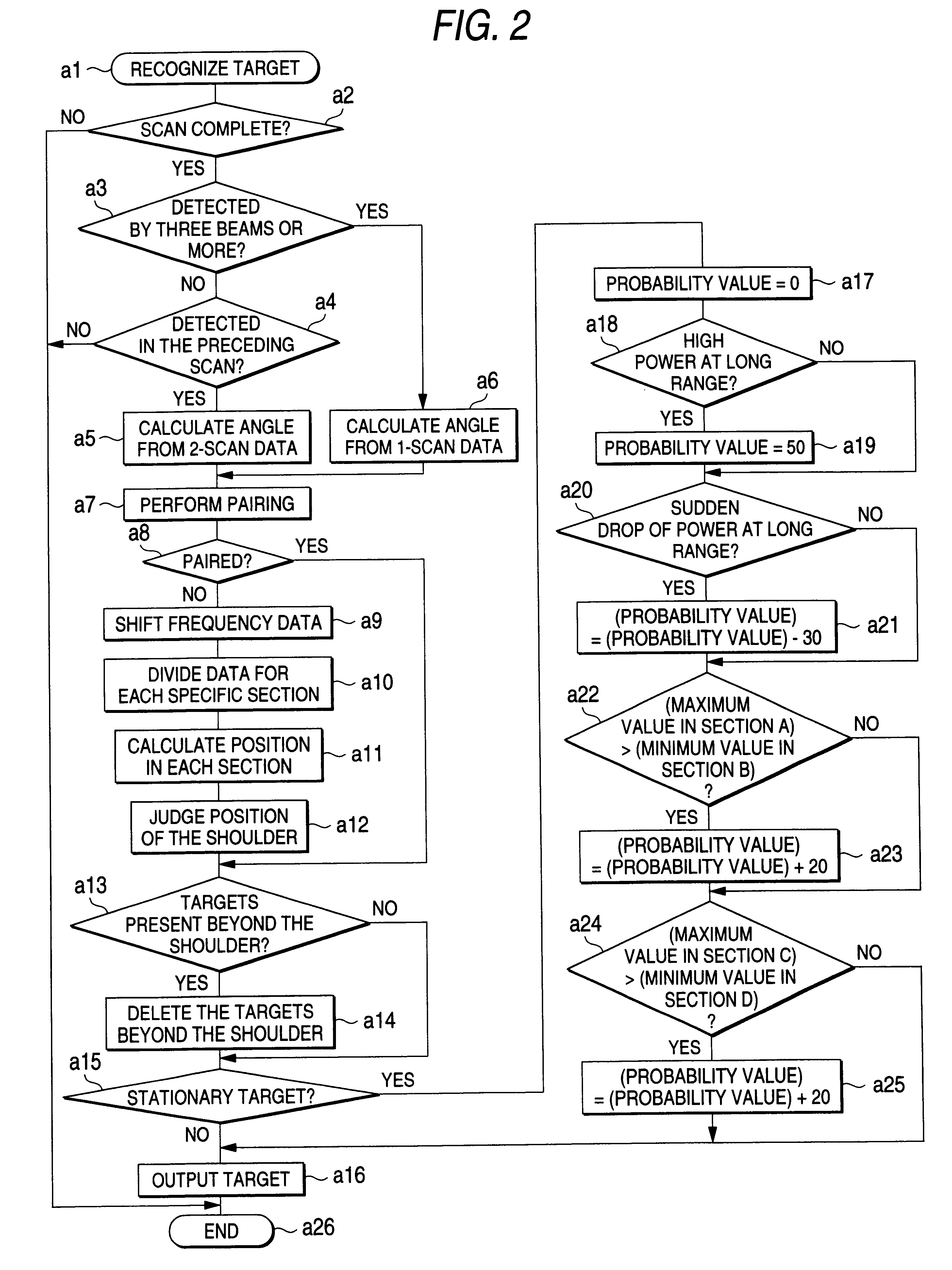
FIG. 2 shows the processing procedure of the object recognition circuit 30 as the invention. When a target is recognized, the procedure from step a1 starts. In step a2, it is determined whether or not a single scan of the antenna 23 by the scanning mechanism 24 is complete. In case it is determined that the scan is complete, it is determined whether or not a reflected signal from the target 22 is detected via at least three beams of the antenna 23 with a beam direction 23a facing a single direction while sending an exploration signal in step a3. In case it is determined that the reflected signal is not detected via at least three beams, it is determined whether or not the target recognized in the preceding scan is detected in step a4. In case the target is not detected, execution returns to step a2. In case it is determined that the target 22 detected in the preceding scan is recognized, the beam angle is calculated from the preceding and current scan data in step a5. In case it is ...

third embodiment

FIG. 5 shows the procedure for estimating the position of the target 22 and the relative velocity in case the vehicle 32 approaches the target 22 at a high speed, as the invention. After the target is recognized in step b1, it is determined whether or not the range is shorter than the reference range in step b2. In case it is determined that the range is shorter than the reference range, it is determined whether or not the relative velocity is higher than the reference velocity. In case it is determined that the range is not smaller than the reference range in step b2, or in case it is determined that the relative velocity is not higher than the reference velocity in step b3, the range and the relative velocity to the target 22 are calculated using the data in the frequency rise section and the frequency drop section in step b4, same as the typical FM-CW system. In case it is determined that the relative velocity is higher than the reference velocity in step b3, data in the frequenc...

fourth embodiment

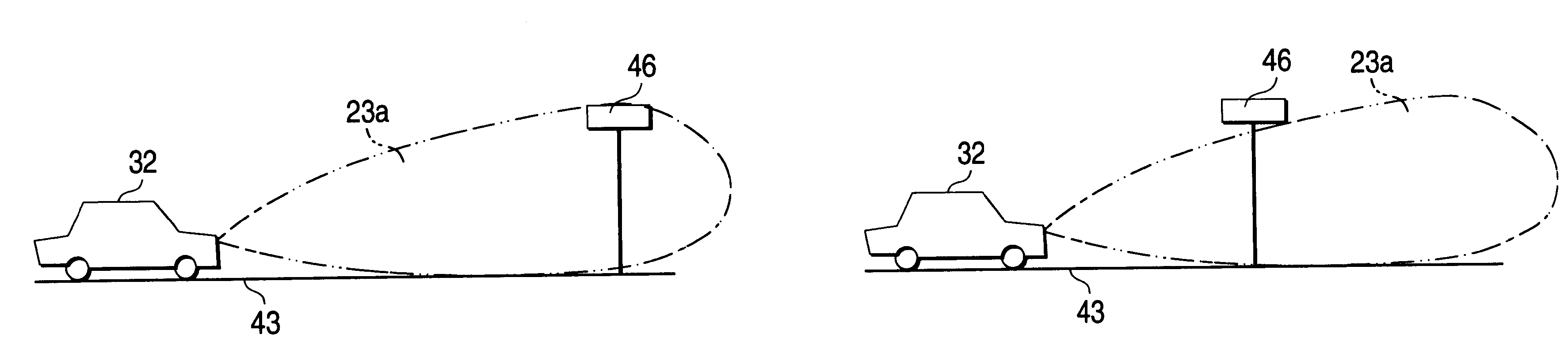
FIG. 7 shows an example of a philosophy that determines whether or not a stationary object on the road can be cleared in an approach to the object as the invention. When a target 42 where an exploration signal 40 transmitted from an antenna 23 of the vehicle 32 reflects to become a reflected signal 41 is relatively higher than the road surface 43, a multipath error takes place. The reflected signal 41 is either a signal directly received by the antenna 23 or a signal reflected off a road surface 43 and received by the antenna 23. This causes a phase difference between reflected signals 41 that are received based on the path difference. When the reflected signals 41 cancel each other due to this phase difference, the reflected signal level drops.

FIGS. 8A and 8B show a difference of the signal level aused by the height of the target 42 from the road surface 43 when the signal level of the reflected signal 41 relative to the range is represented as a power. FIG. 8A shows the variation ...


PUM


Abstract

A target 22 is explored by transmitting an exploration signal 40 at a certain angle while scanning an antenna 23. In the go and return exploration the angle for transmitting the exploration signal is shifted. It is possible to detect the direction of the target 22 with the same accuracy as that in exploration with a more minute angle difference, by combining the exploration results with the angle shifted in a plurality of scans. Relative travel of the target 22 that accompany a plurality of scans is considered as a Doppler shift and a combination of data is used considering the frequency shift. Data that cannot be combined is treated as an unwanted reflective object and the position where unwanted reflecting objects assemble is obtained and the position is determined as a shoulder. The height of a stationary target is determined from the variation in the reflected signal level in an approach to the stationary target.

Description

1. Field of the InventionThe present invention relates to a motor-vehicle-mounted radar apparatus mounted on a vehicle and used to explore obstacles such as other vehicles traveling around the vehicle, for example, ahead of the vehicle, as targets thus securing safety of driving.2. Description of the Related ArtConventionally, motor-vehicle-mounted radar apparatus that explores obstacles of a vehicle in the direction of traveling has been developed. As motor-vehicle-mounted radar apparatus, the FM-CW system is employed in which an exploration wave as a continuous sending wave frequency-modulated using a triangular wave as a modulating wave and a beat component caused by a reflected wave from a target are extracted as a beat signal, and the relative velocity and relative range to the target are obtained based on the frequency of the beat signal. Related arts concerning the FM-CW system radar apparatus are disclosed, for example, in the Japanese Patent Laid-Open No. 111395 / 1977, the J...

Claims


Application Information

Patent Timeline
IPC IPC(8): G01S13/00G01S13/93G01S13/34G01S13/42G01S13/536G01S13/50G01S13/931
CPCG01S13/34G01S13/426G01S13/931G01S13/536G01S2013/462G01S2013/9321G01S2013/9346G01S2013/9353G01S2013/93185G01S2013/932
Inventor KISHIDA, MASAYUKIONO, DAISAKUHIGASHIDA, HIROFUMI
Owner FUJITSU GENERAL LTD
Why Eureka
Try Eureka