
Bicycle accessory mounting apparatus

Inactive Publication Date: 2002-08-13
MOORE DAVID B +1
View PDF19 Cites 30 Cited by
  • Summary
  • Abstract
  • Description
  • Claims
  • Application Information

AI Technical Summary

Benefits of technology

Another object is to provide a bicycle accessory mount that is multifunctional, flexible, and rugged.
Another object is to provide a bicycle accessory mount that will aid in the learning-to-ride process of youngsters, with an improved balance control to reduce the risk of injury to the trainer and trainee due to falls, with an adjustable balance arm for bicycle trainers to adjust handle height and position along side of the bicycle to improve balance control, and that reduces the training cycle.

Problems solved by technology

U.S. Pat. No. 6,120,050 to Stephen L. Tillim (Sep. 19, 2000) is a one-piece bicycle-training device that can be positioned to vary the relative position of trainer along the side of the bicycle, but the height of the trainer's handle is not adjustable.
In this case, the trainer's physical well being, as well as the beginning bicyclist, is at risk with this device.
The device has an adjustable trainer's handle for the varying height and physical limitations of the trainer, but is a multiple piece construction with a complex handle attachment mechanism.
It is a one-piece construction, but the height of the trainer's handle is not adjustable.
None of these devices have applications other than bicycle training.
The major draw back to bicycle transportation has been the limitations of carrying essential items.
For long distances, the backpack will fatigue the rider resulting in a trip taking much longer than expected.
There is also the possibly of injury to the bicyclist from prolonged carrying of the backpack and from a fall while carrying the backpack.
Small pouches attached to the handlebars may impair the bicyclist's ability to steer or brake.
Also, the pouches can only carry a few items, such as a tool kit.
This limited carrying capability is inadequate for any bicycle trips longer than a few hours.
The small carriers mounted over the rear wheel are limited to holding a small bag or backpack, but is plagued with a balancing problem.
None of these devices have applications other than carrying a lock or shackle.
Two such child seats, U.S. Pat. No. 5,890,759 to David B. Ross (Apr. 6, 1999) and U.S. Pat. No. 5,653,500 to Anthony Amore (Aug. 5, 1997), are relatively complex in design with multiple parts.
Therefore, these two devices have no other applications other than carrying a child's seat.

Method used


Image

  • Bicycle accessory mounting apparatus
  • Bicycle accessory mounting apparatus
  • Bicycle accessory mounting apparatus

Examples


Embodiment Construction

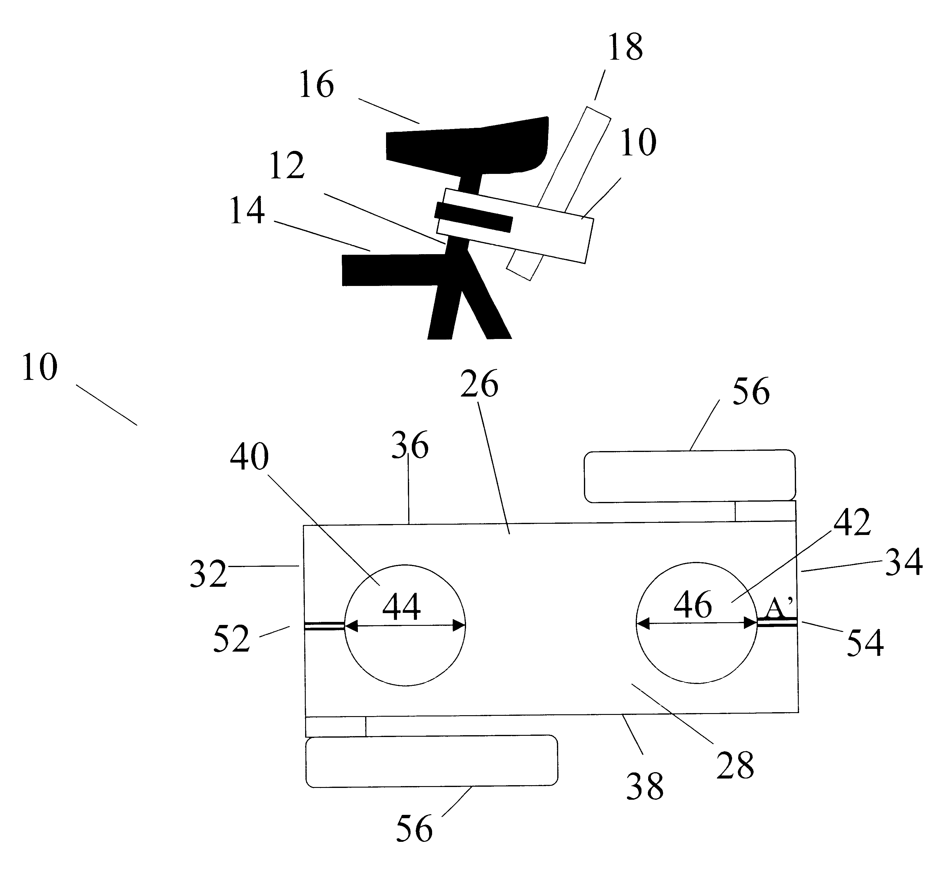
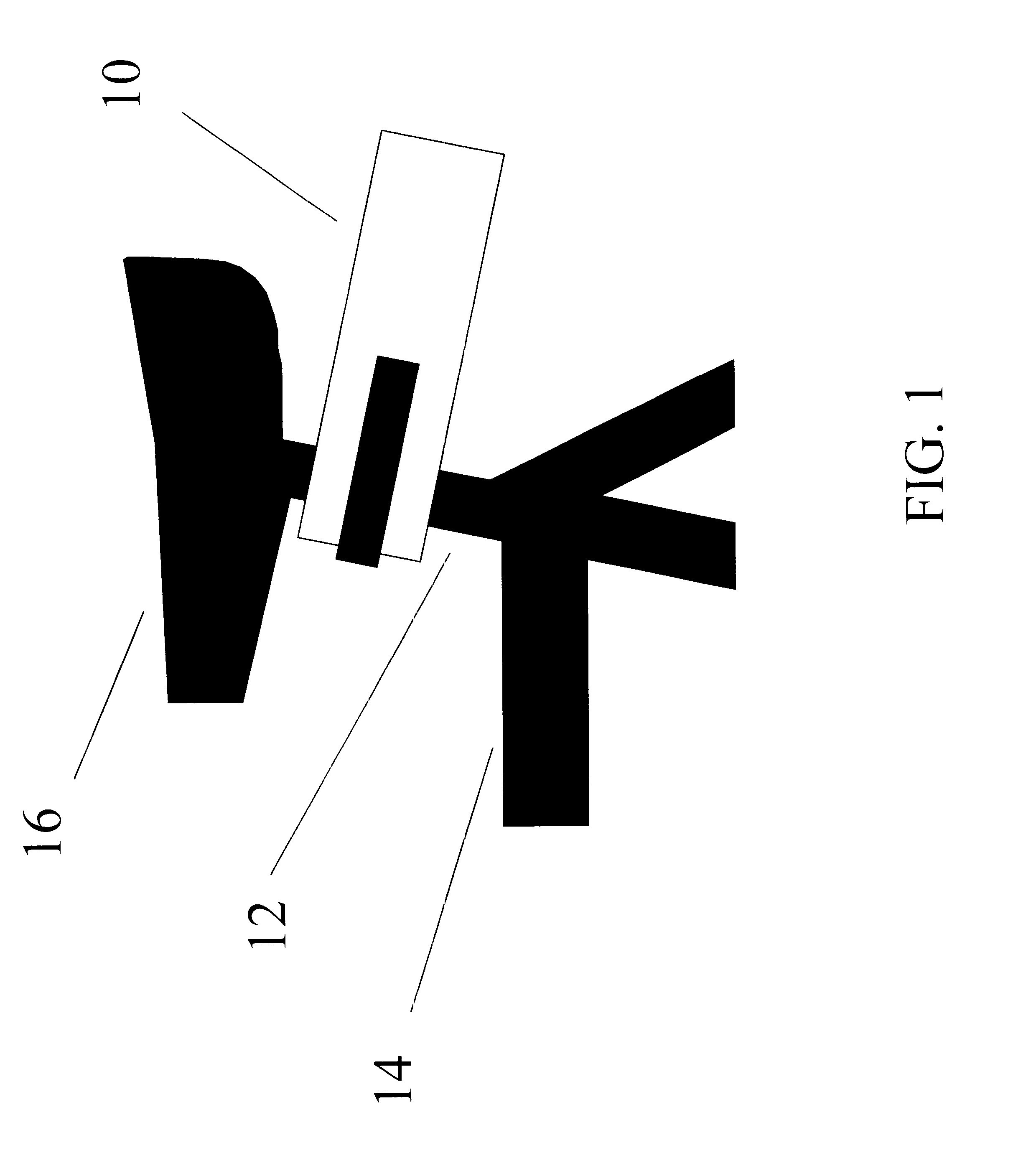
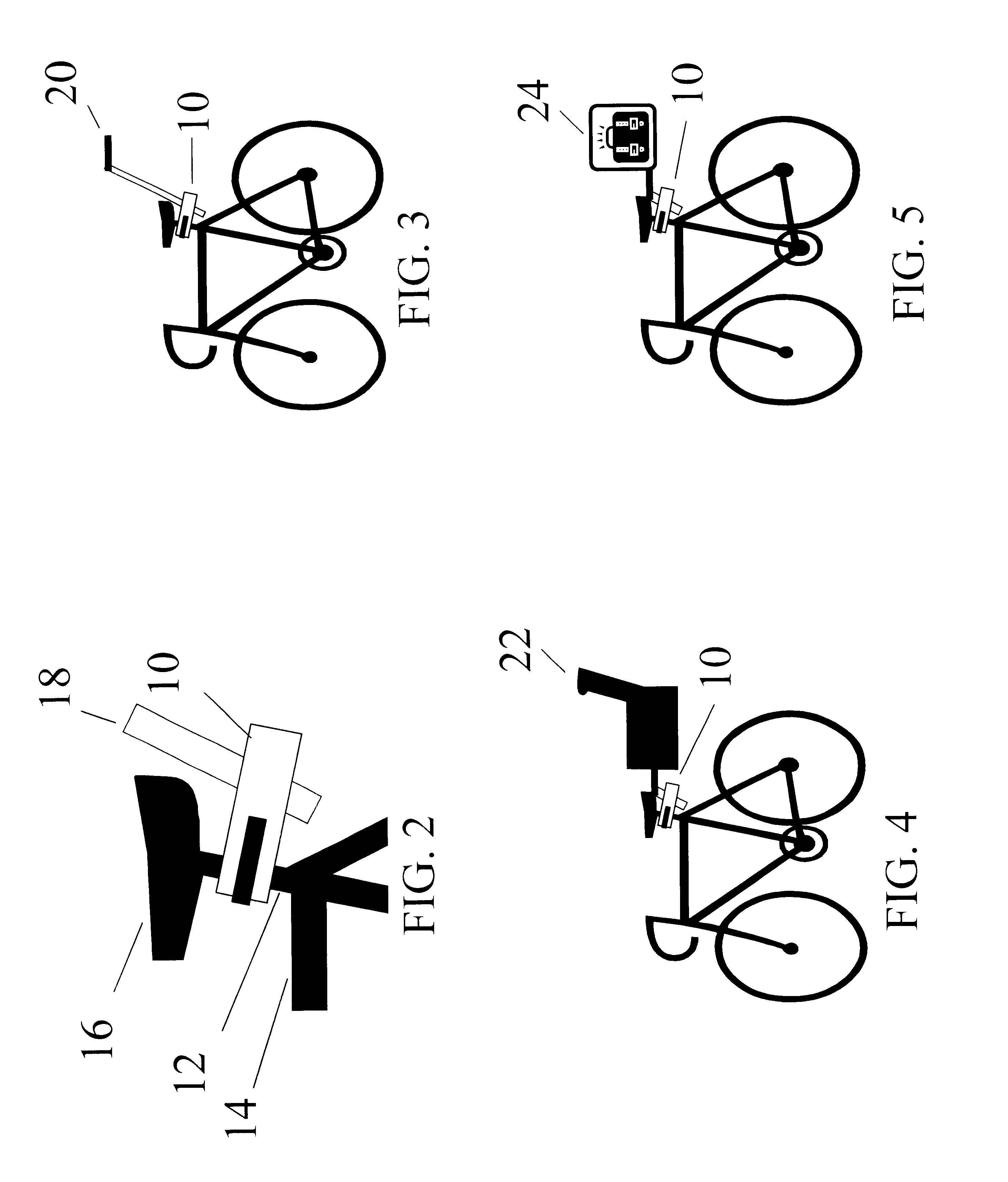
Referring to FIG. 1, a bicycle accessory mounting apparatus 10 is connected to a bicycle seat post 12 that couples the bicycle accessory mounting apparatus 10 to a bicycle 14 (partially shown). The bicycle accessory mounting apparatus 10 is positioned below the seat 16 at a vertical height sufficient to receive the accessory shaft 18 (see FIG. 2) without interference by the seat 16. As illustrated in FIGS. 3, 4, and 5, the bicycle accessory mounting apparatus 10 is used in combination with a bicycle training handle 20, child bicycle seat 22, and a cargo carrier 24. Other accessories not mentioned herein are also to be contemplated and within the scope of the present invention.

As illustrated in FIG. 6 and FIG. 7, the bicycle accessory mounting apparatus 10 comprises a block 26 and two locking devices 56. The block 26 is made of suitable material, e.g., aluminum, titanium, stainless steel, graphite, plastic, or other polymer, to withstand the operating load conditions. The block 26 is...


PUM


Abstract

A bicycle accessory mounting apparatus for releasably securing a bicycle accessory quickly and effectively to a bicycle seat post. The bicycle accessory mounting apparatus comprises a block having two holes, two gaps, and two snap lock quick connect mechanisms at opposing ends.

Description

None.Not ApplicableREFERENCE TO A MICROFICHE APPENDIXNot ApplicableThe present invention is directed toward an improved bicycle accessories mounting device for carrying various bicycle accessories, including but not limited to, a learn-to-ride balance handle, saddle bags, tool kit, back-pack holder, a child carrier, as well as other after market accessories. The device is secured to the bicycle seat post of any type of bicycle. Accessories are attached to the device securely and safely held under any type of terrain conditions.One application of the present invention overcomes the problems and disadvantages of training wheels or other means of supporting an individual learning to ride a bicycle. The bicycle accessory mounting apparatus in combination with a training handle allows a supervising or teaching individual to walk or run along with learning individual maintaining balance and support. The adjustable handle also provides improved ergonomics for the trainer. The present inven...

Claims


Application Information

Patent Timeline
IPC IPC(8): B62J1/16B62J1/00B62J7/00B62J7/04B62J9/00
CPCB62J1/16B62J7/04B62J9/001B62J9/23
Inventor MOORE, DAVID B.MOORE, CHARLES L.
Owner MOORE DAVID B
Learn More