Vapor-adsorbent filter for reducing evaporative fuel emissions, and method of using same

a technology of evaporative fuel and filter, which is applied in the direction of filtration separation, combustion-air/fuel-air treatment, separation process, etc., can solve the problems of contributing to air pollution

Inactive Publication Date: 2002-08-13
FRAM GROUP IP +1
View PDF23 Cites 82 Cited by
  • Summary
  • Abstract
  • Description
  • Claims
  • Application Information

AI Technical Summary

Benefits of technology

It is a further object of the present invention to provide a method and apparatus for removing residual fuel vapors from an engine's intake system, downstream of the throttle body, after the engine has been turned off.
It is yet a further object of the invention to provide a filter for adsorbing fuel vapors out of ambient air, in which the filter minimizes pressure drop therepast, so as not to interfere with the free flow of air to the engine.

Problems solved by technology

While a vehicle is sitting over time after use, this evaporated fuel may pass outwardly through the intake manifold, the intake air ducts and air filter, and may escape into the atmosphere, thus contributing to air pollution.

Method used


Image

  • Vapor-adsorbent filter for reducing evaporative fuel emissions, and method of using same
  • Vapor-adsorbent filter for reducing evaporative fuel emissions, and method of using same
  • Vapor-adsorbent filter for reducing evaporative fuel emissions, and method of using same

Examples


first embodiment

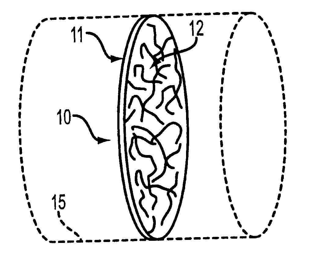
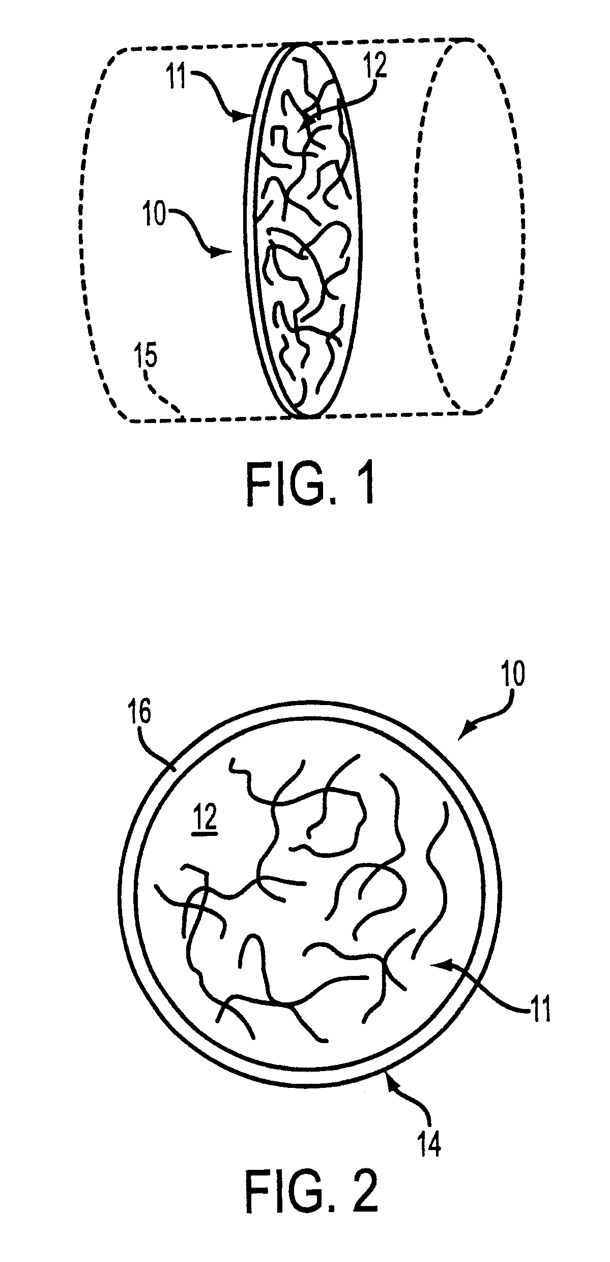
Referring now to FIGS. 1-7, a filter in accordance with the invention is shown generally at 10. The filter 10 is provided for placement in an intake airflow passage 15, associated with an internal combustion engine (not shown). The airflow passage 15 does not form a part, per se, of the present invention. The filter 10 may be placed extending across a flow passage such as, for example, a portion of an intake manifold or a throttle body.

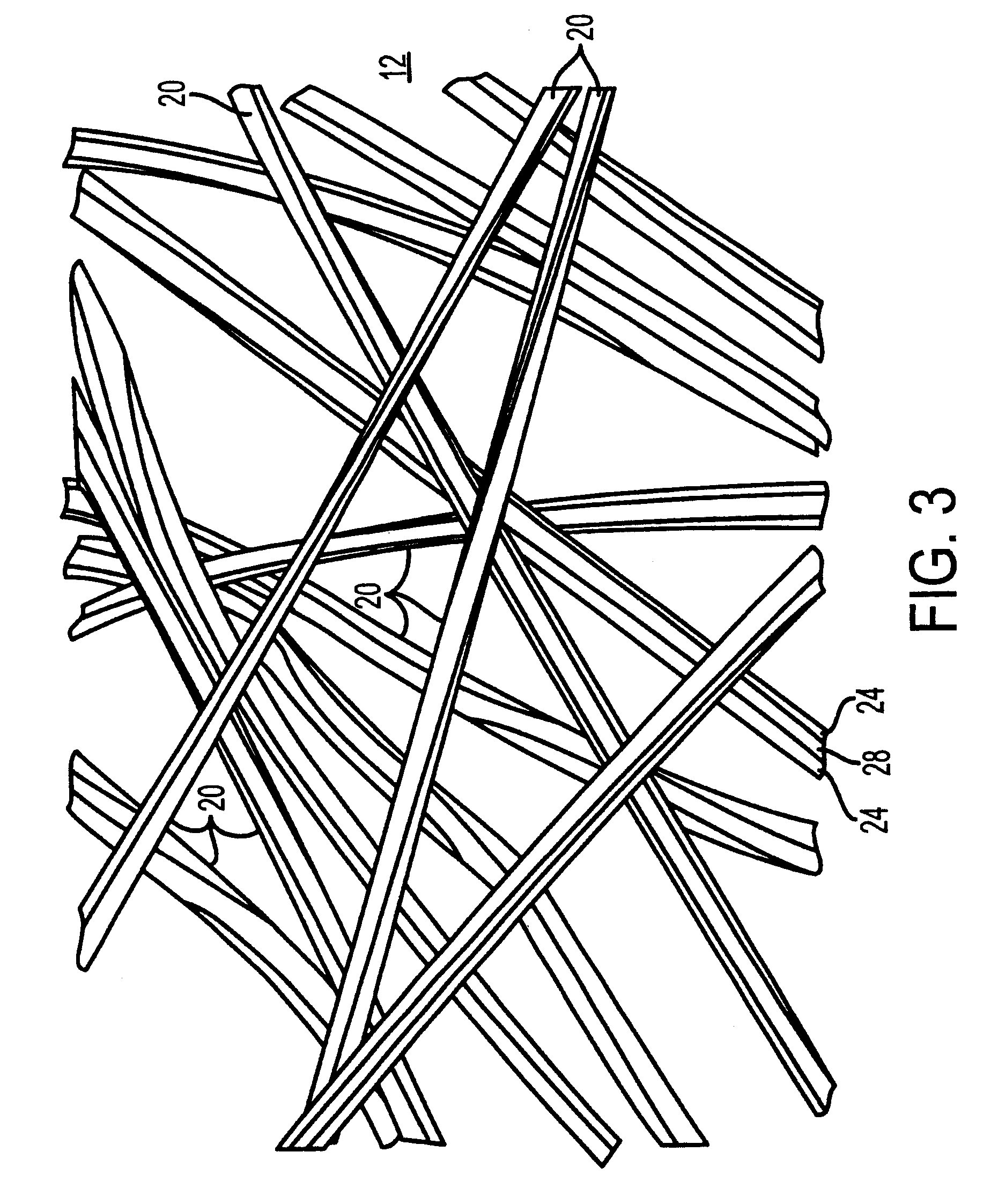
The filter 10 includes a filter element 11, which comprises a porous non-woven fiber web 12 made up of a plurality of individual fibers 20 (FIG. 3). In the filter element 11, the fiber web 12 is preferred to be made in a loose weave with relatively large air pockets between the fibers, in order to minimize pressure drop thereacross.

The pressure drop across the filter 10 is less than 5 inches of mercury at 5,000 cubic feet per minute of flow. Preferably, the pressure drop is less than 3 inches of mercury at 5,000 cubic feet per minute of flow.

Optionall...

second embodiment

Referring now to FIG. 8, another embodiment of a filter 210 is shown in accordance with a second embodiment of the invention. In the illustration, a throttle plate 202 is shown disposed within an intake air flow passage 215 of a throttle body 205, which is shown in phantom for purposes of illustration. The throttle plate 202 is generally conventional, and does not form a part of the present invention.

A circular disc-shaped filter element 211, in accordance with a second embodiment of the present invention, is affixed to the rear surface of the throttle plate 202. The filter element 211 may be glued on, or otherwised attached to the throttle body in conventional fashion.

The filter element 211 includes a porous non-woven fiber web 212 made up of a plurality of individual fibers 20. The fibers 20 making up the filter element 211 are the same as previously discussed in connection with the first embodiment.

The fibers 20 are impregnated with a fuel vapor-adsorbing compound, as discussed h...

third embodiment

Referring now to FIG. 9, another filter assembly 310 is shown, in accordance with a third embodiment of the invention. In the embodiment of FIG. 9, a pair of semi-circular opposed baffle plates 302, 304 are provided for placement in an intake air flow passage 315, associated with an internal combustion engine (not shown). The filter assembly 310 may be placed in a flow passage 315 such as, for example, a portion of an intake manifold.

These baffle plates 302, 304 may be made foraminous or solid, according to the application. The baffle plates 302, 304 are each pivotally mounted in the air flow passage 315, so as to be movable between a horizontal, open position when the engine is running, and a vertical, closed position when the engine is off.

The filter 310 also includes a pair of filter elements 306, 308, made in the same semi-circular D-shape as the baffle plates, and attached to the back surface thereof by any appropriate method. Each of the filter elements includes a porous nonwo...


PUM

PropertyMeasurementUnit
angleaaaaaaaaaa
diameteraaaaaaaaaa
diameteraaaaaaaaaa

Abstract

A filter, for use in removing residual fuel vapors from within an engine's intake system, includes a filter element having a plurality of fibers, for placement in communication with an intake air flow passage. Each of the fibers has an internal cavity formed therein, and a longitudinally extending slot formed therein extending from the internal cavity to the outer fiber surface. The filter also includes a hydrocarbon-absorbing material disposed within the internal cavities of the fibers. The hydrocarbon-absorbing material may be a solid material such as, e.g., carbon, or may be a liquid such as a relatively non-volatile organic solvent. Alternatively, the material may be a combined solid and liquid. In one embodiment, each of the elongated fibers includes a central stem and a plurality of lobes extending outwardly from the central stem, with a longitudinally extending slot defined between adjacent lobes. Specific useful filter configurations are detailed.

Description

1. Field of the inventionThe present invention relates to a filter for reducing evaporative fuel emissions from an internal combustion engine. More particularly, the present invention relates to a filter for placement on an engine, downstream of a throttle plate, to adsorb evaporative emissions after the engine has been turned off.2. Description of the Background ArtThe great majority of internal combustion engines in use today are fuel-injected engines. When a fuel-injected engine is switched off after use, a small amount of residual fuel volatilizes and escapes from the injector tips. While a vehicle is sitting over time after use, this evaporated fuel may pass outwardly through the intake manifold, the intake air ducts and air filter, and may escape into the atmosphere, thus contributing to air pollution. It would be desirable to minimize this type of inadvertent evaporative emissions leakage.Many different types of filters are known for use in filtering evaporative fuel emission...

Claims


Application Information

Patent Timeline
Patent Type & Authority Patents(United States)
IPC IPC(8): B01D53/04F02M25/08F02M35/02F02M35/04F02M35/10
CPCB01D53/0407F02M25/08F02M35/024F02M35/10019F02M35/10222F02M35/10281F02M35/10334F02M35/10013B01D2253/102B01D2253/30B01D2257/702Y10T428/2975Y10S55/19F02M35/0218
Inventor LOBOVSKY, ALEXMATRUNICH, JAMESBAUSE, DANIELJONES, GORDONROHRBACH, RONALDZULAUF, GARYUNGER, PETER
Owner FRAM GROUP IP
Why Eureka
Try Eureka