
Device and method for correcting the baseline wandering of transmitting signals

a transmitting signal and baseline technology, applied in the field of devices and methods for correcting the baseline wandering of transmitting signals, can solve problems such as errors in the output signals of receivers

Inactive Publication Date: 2002-08-13
REALTEX SEMICON
View PDF8 Cites 38 Cited by
  • Summary
  • Abstract
  • Description
  • Claims
  • Application Information

AI Technical Summary

Problems solved by technology

When the DC voltage potential is wandering downward or upward to a certain extent, i.e., when it is lower or higher than the threshold potential, it will cause error in the output signals of the receiver.

Method used


Image

  • Device and method for correcting the baseline wandering of transmitting signals
  • Device and method for correcting the baseline wandering of transmitting signals
  • Device and method for correcting the baseline wandering of transmitting signals

Examples


Embodiment Construction

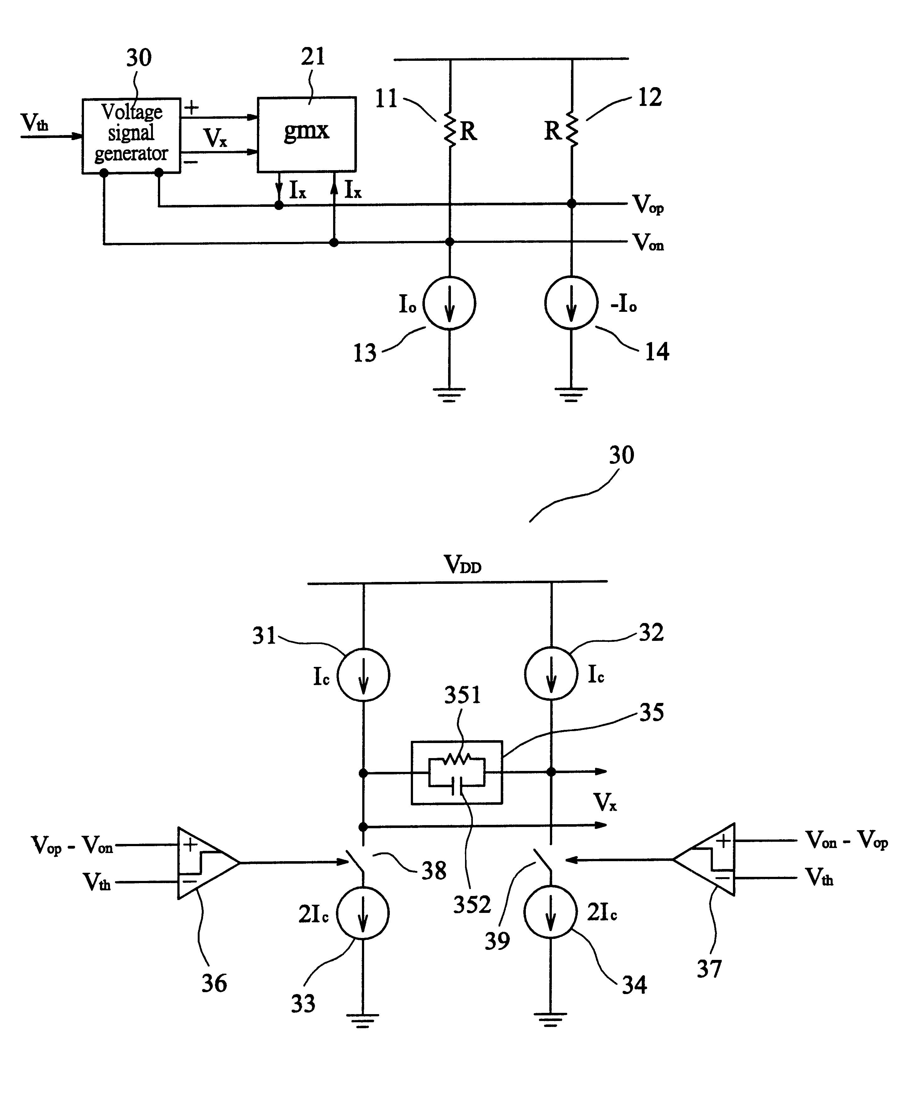
FIG. 3 is a circuit diagram showing the device for correcting the baseline wandering of transmitting signals used in a receiver in accordance with the present invention. In accordance with the present invention, the device 20 comprises a voltage signal generator 30, and a compensation current source 21 controlled by the control voltage Vx output from the voltage signal generator 30. The current output terminals Iop, Ion of the compensation current source 21 are respectively connected to the voltage output terminals Vop and Von of the equivalent circuit (referring to FIG. 1) of the receiver. In addition, the compensation current Ix of the compensation current source 21 is controlled by the control voltage Vx, i.e.,

Ix=Vx*gmx (4)

wherein, gmx is the transconductance of the transconductor. Thus, by compensating the variation of output current lo as a result of induction of the transformer with the compensation current value Ix, the baseline wandering is effectively corrected.

FIG. 4 shows...


PUM


Abstract

A device and method for correcting the baseline wandering of transmitting signals are disclosed. The present method and device are used to correct the baseline wandering of the first output terminal and the second output terminal of a receiver as a result of induction effect of the transformer. The present device comprises a compensation current source including a first compensation output terminal and a second compensation output terminal which are respectively connected to the first output terminal and the second output terminal of the receiver. The device further includes a voltage signal generator for generating a control voltage to control the compensation current source. The voltage signal generator employs the voltage difference of the first output terminal and the second output terminal of the receiver and a reference voltage to control the control voltage. Thereby, the compensation current value of the compensation current source is supplied to the first output terminal and the second output terminal of the receiver and is used to correct the baseline wandering.

Description

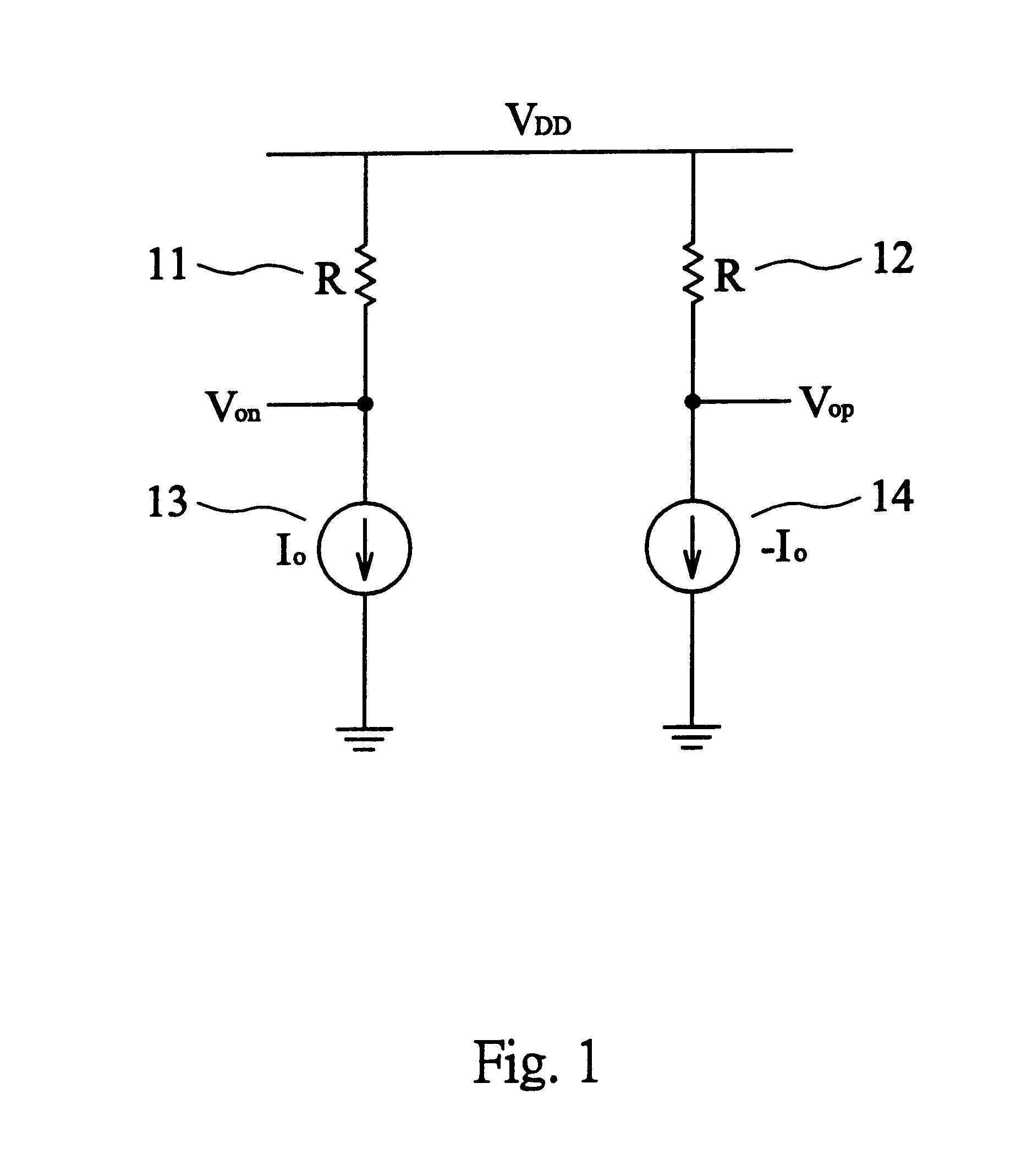
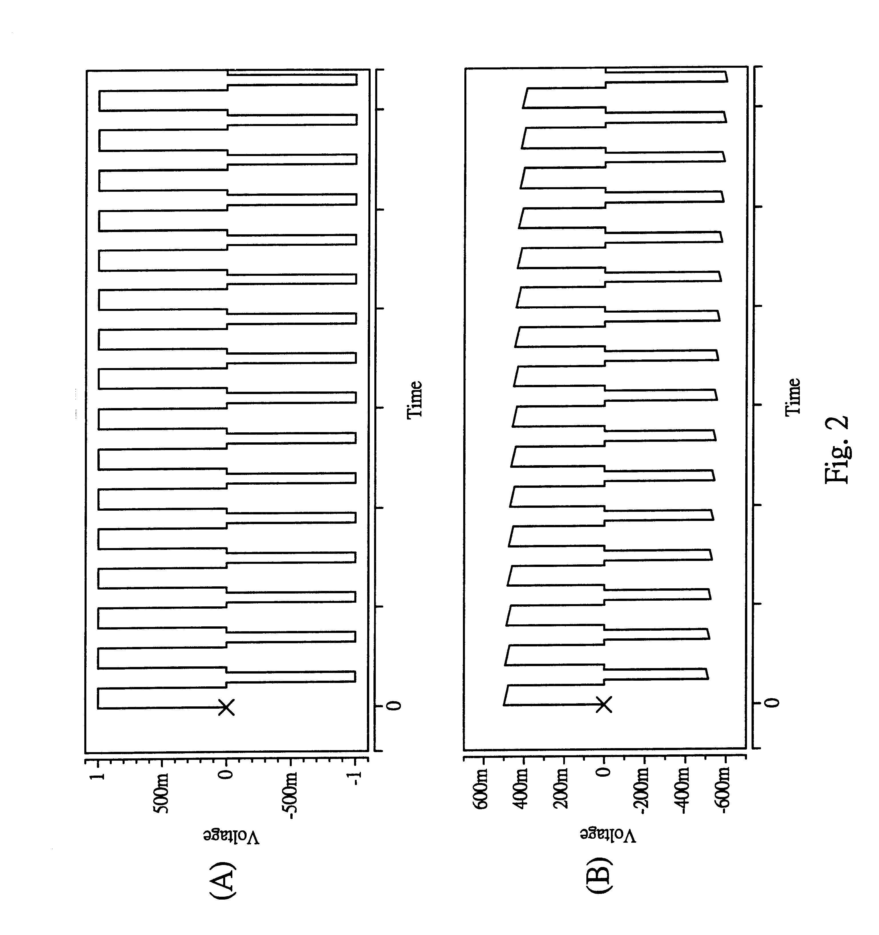
A. Field of the InventionThe present invention relates to a device and method for correcting the baseline wandering of transmitting signals, and in particular, a device and method for correcting the baseline wandering of transmitting signals by employing a compensation current source to compensate the baseline wandering.B. Description of the Related ArtFIG. 1 is an equivalent circuit diagram of a conventional receiver 10 comprising resistors 11,12, and current sources 13, 14. The output voltage Vo of the receiver 10 is denoted by Vo=Vop-Von, that is, ##EQU1##wherein, Vo is the output voltage of the receiver 10, and R is equivalent output impedance, and Io is the current of the current source received by transformer, and assuming that the effect of the wires or cables can be negligible or is equalized.In addition, due to the fact that the receiver is output by the transformer, and therefore, the output voltage Vo(S) after Laplace transformation is represented as follows: ##EQU2##wher...

Claims


Application Information

Patent Timeline
Patent Type & Authority Patents(United States)
IPC IPC(8): H04L25/02H04L25/06
CPCH04L25/0266H04L25/0272H04L25/028H04L25/0292H04L25/061
Inventor HUANG, CHEN-CHIH
Owner REALTEX SEMICON
Learn More