Tank filling apparatus and method

Inactive Publication Date: 2002-08-20
CALIFORNIA INT CHEM CORP
View PDF9 Cites 11 Cited by
  • Summary
  • Abstract
  • Description
  • Claims
  • Application Information

AI Technical Summary

Benefits of technology

The present invention has several advantages over the prior art. First, the operating pressures of the present invention range between 0 and 150 pounds per square inch gauge (psig). Thus, the added capital and maintenance expenses associated with the prior art vacuum systems for gas purging have been minimized. Second, the amount of chlorine lost during processing while using this invention has been drastically reduced to below 1 ppd. The disposal costs for the purged chlori

Problems solved by technology

Vacuum systems, however, are expensive both from an equipment and a maintenance standpoint because special equipment is required to construct and maintain a vacuum system.
Caustic material is expensive, and after the caustic material has been depleted, the purged waste material, containing caustic and the neutralized chlorine, must be properly disposed.
During the filling proce

Method used


Image

  • Tank filling apparatus and method
  • Tank filling apparatus and method
  • Tank filling apparatus and method

Examples


Embodiment Construction

Illustrations of preferred construction, design, and methods of operation of the invention are set forth below with specific references to the Figure. However, it is not the intention of the inventor that the scope of his invention be limited to these preferred embodiments.

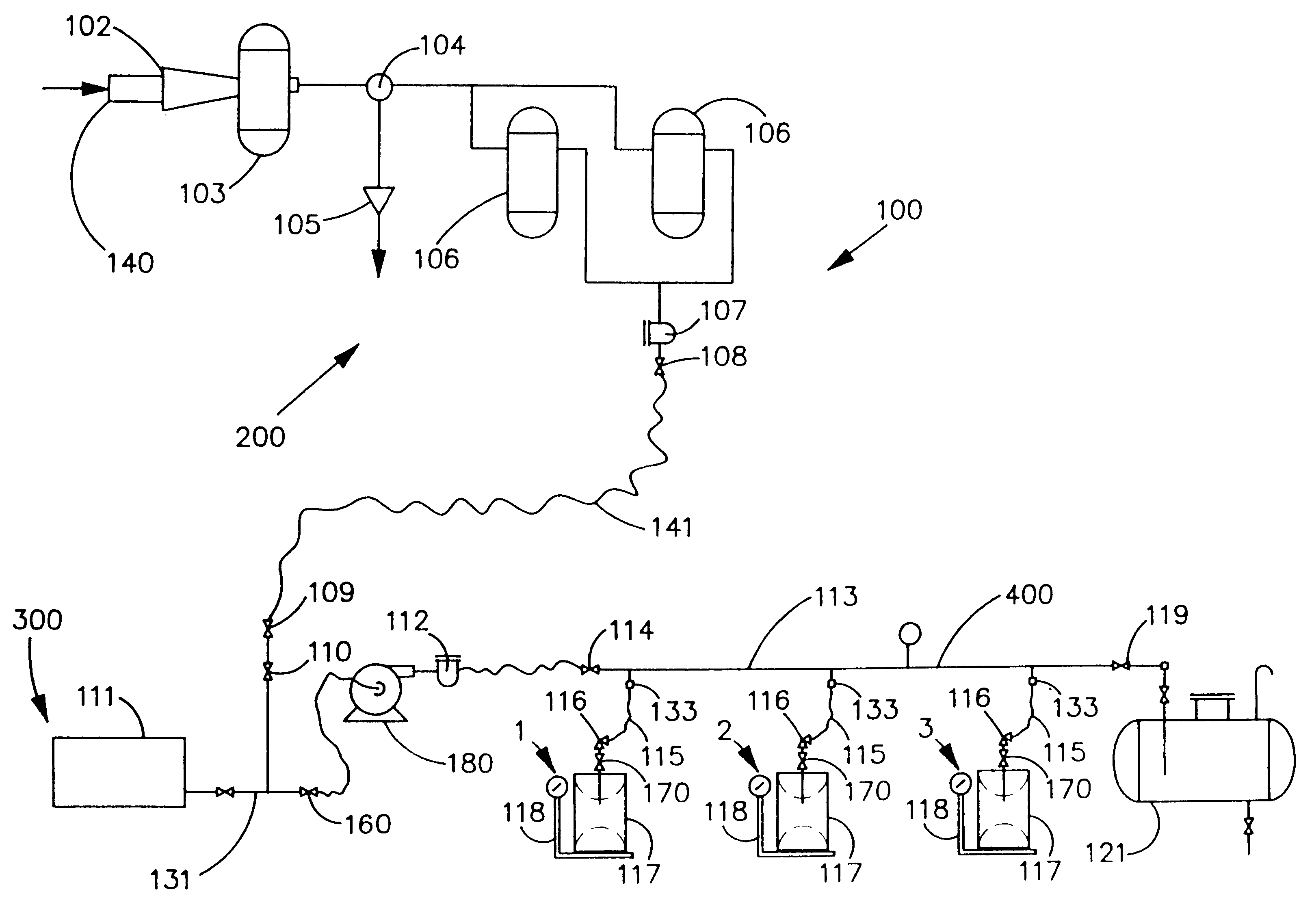
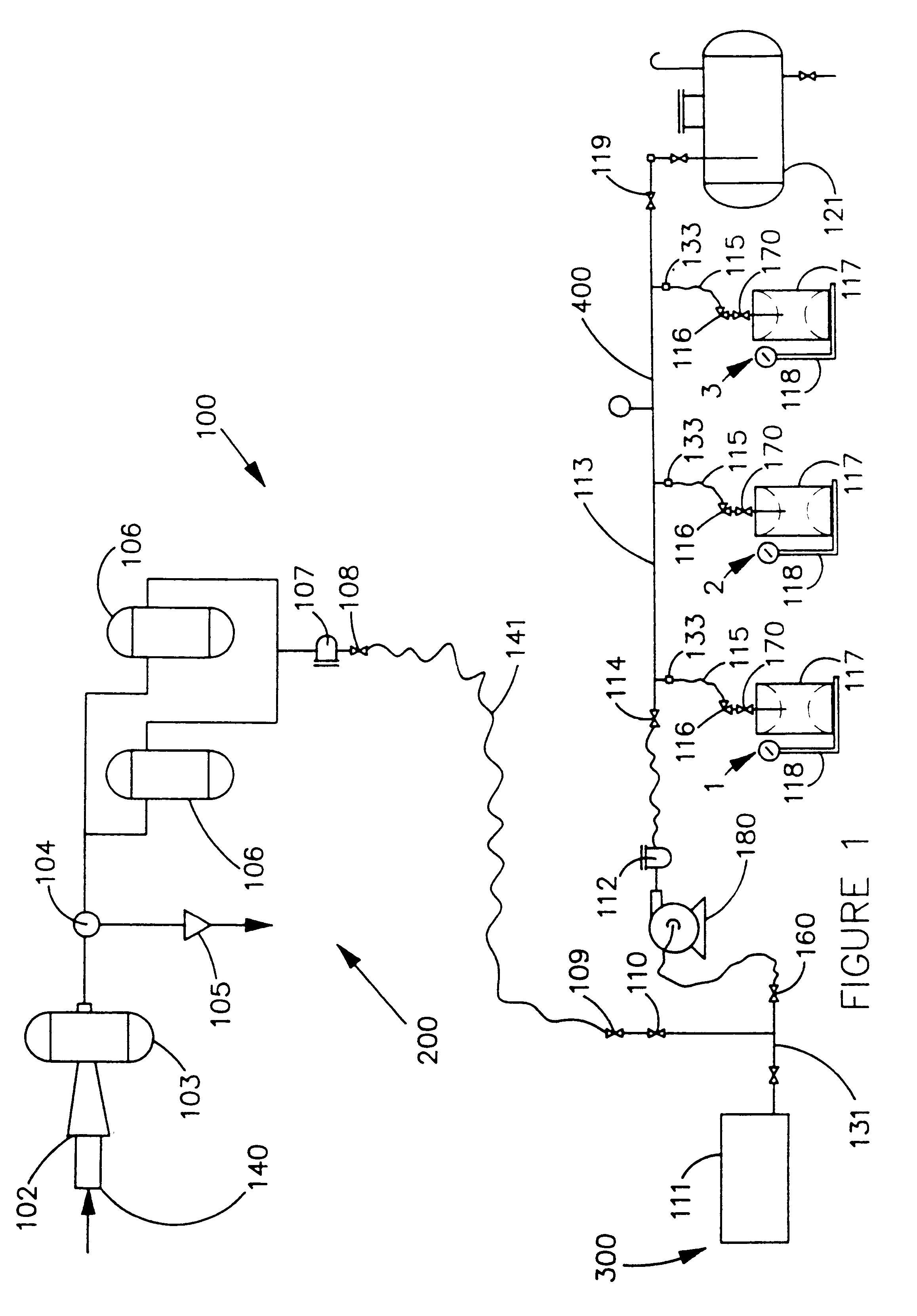
As shown in FIG. 1, chlorine tank filling apparatus 100 generally comprises a manifold 400 having a substantially particle-free, dry purge gas source 200 connectable thereto and having a substantially particle-free process material source 300 connectable thereto. "Process material" and "chlorine" are used interchangeably throughout. It is understood that this invention has application beyond the filling of chlorine cylinders and may be used to fill cylinders with other materials. Thus, process material is defined as the material being transported from tank 111 to cylinders 117. Purge gas flows from source 200 into manifold 400 through valve 109, valve 110, connection tee 131, valve 160, pump 180, filter 112, valve...


PUM

PropertyMeasurementUnit
Fractionaaaaaaaaaa
Pressureaaaaaaaaaa
Pressureaaaaaaaaaa

Abstract

An apparatus and method for transferring liquid chlorine or other process material from a larger container to one or more smaller containers, including a valve assembly used to minimize chemical loss, is disclosed herein. The valve assembly minimizes chlorine or other process material loss to the environment by sealing the manifold and the filled cylinder from the environment while the valve assembly is disconnected. The apparatus and methods disclosed herein minimize caustic use associated with purging of the apparatus.

Description

1. Field of the InventionThis invention relates to a method and apparatus for filling liquid and gas cylinders, more particularly an apparatus that reduces the amount of process material gas wasted during the filling and disposal processes.2. Prior ArtPresently, there are a variety of methods and apparatuses used for filling liquid and gas cylinders, including chlorine cylinders. Current methods and apparatuses used for filling chlorine cylinders use vacuum systems within the filling manifold to purge the manifold of chlorine for safe and effective operation. Vacuum systems, however, are expensive both from an equipment and a maintenance standpoint because special equipment is required to construct and maintain a vacuum system.Presently, many chlorine cylinder handling systems comprise a source tank, a filling manifold, a purge gas source, a vacuum system to purge the manifold, and a neutralization tank. After each chlorine cylinder is filled, the filling manifold must be purged of ...

Claims


Application Information

Patent Timeline
IPC IPC(8): F17C5/00F17C6/00F17C13/04
CPCF17C5/00F17C6/00F17C13/04F17C2205/013F17C2227/04F17C2227/041F17C2201/0104F17C2205/0146F17C2205/0323F17C2205/0341F17C2205/0382F17C2221/014F17C2221/016F17C2221/031F17C2221/037F17C2227/0135F17C2227/0157F17C2227/044F17C2227/047F17C2250/01F17C2260/044F17C2265/015
Inventor HEINLE, MICHAEL W.
Owner CALIFORNIA INT CHEM CORP
Why Eureka
Try Eureka