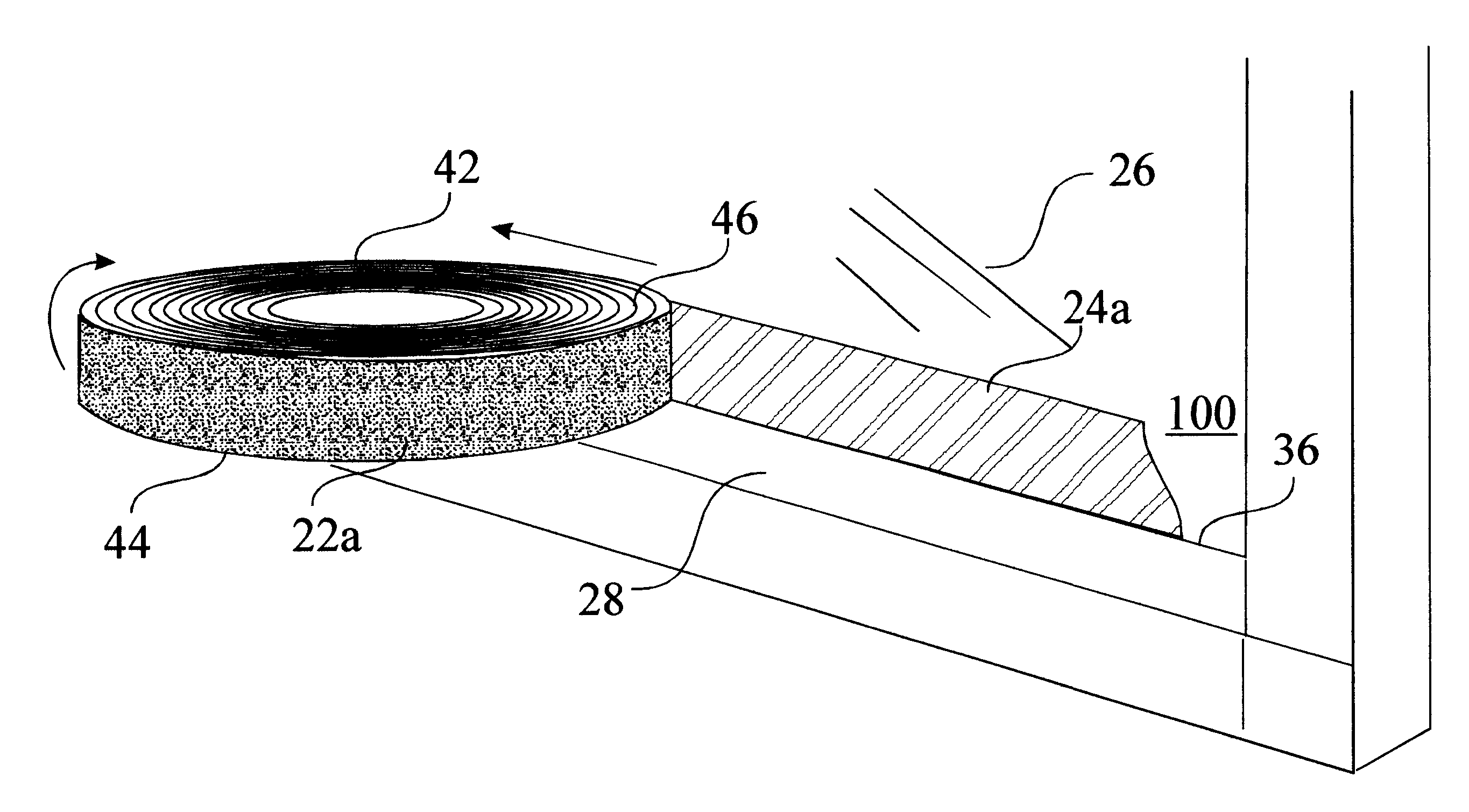
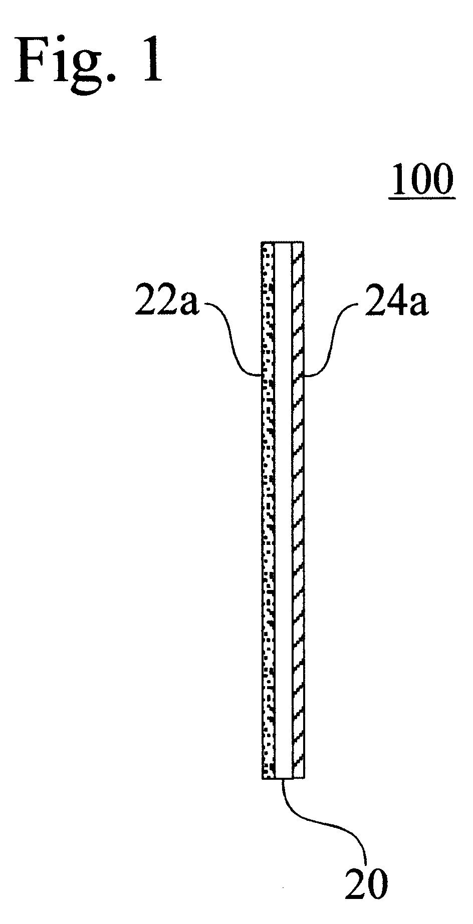
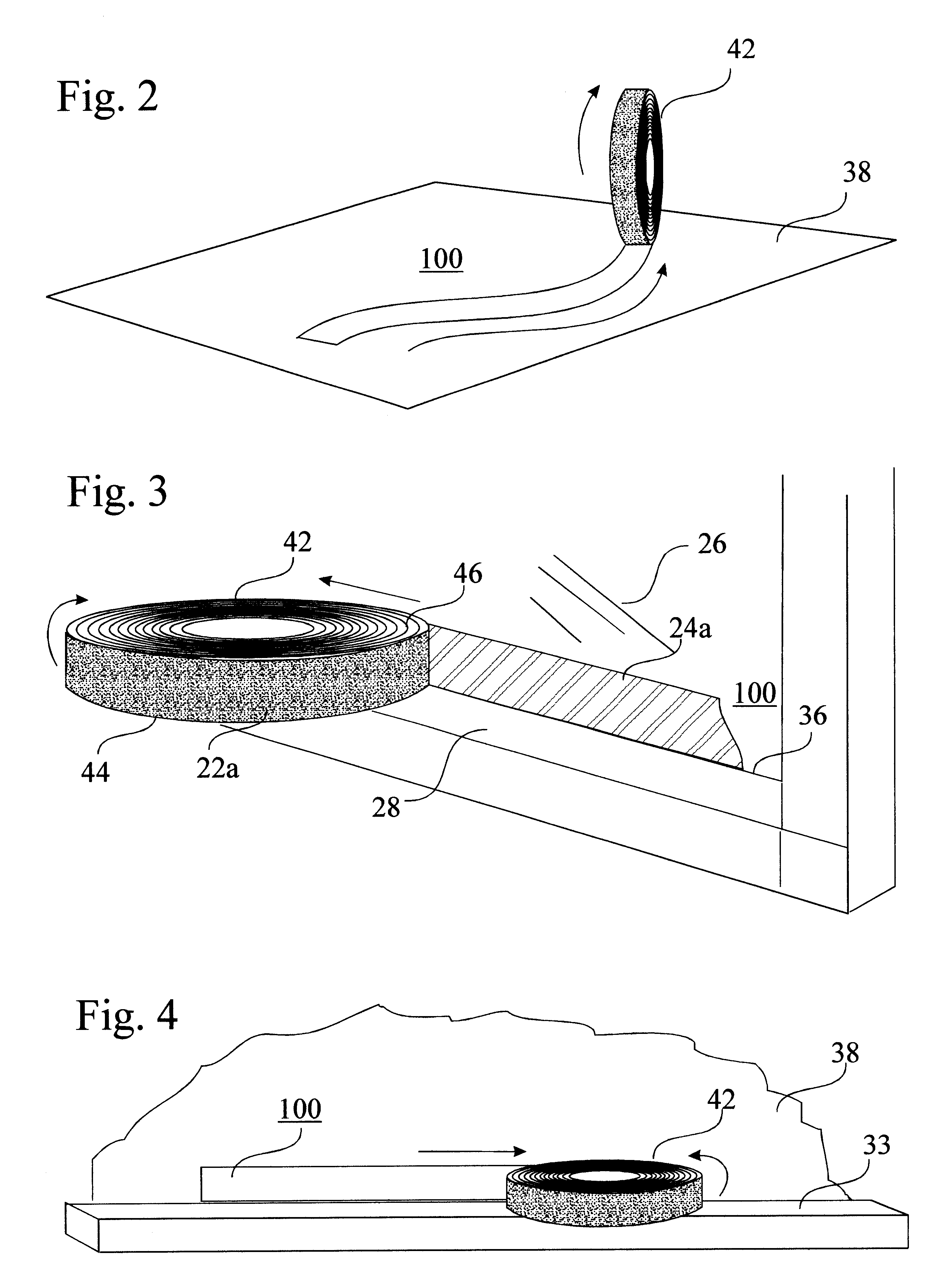
Masking tape
a masking paper and tape technology, applied in the field of masking tapes, can solve the problems of inability to support itself in form, difficulty in pulling away the outer layer used layer, and inability to protect both surfaces,
- Summary
- Abstract
- Description
- Claims
- Application Information
AI Technical Summary
Problems solved by technology
Method used
Image
Examples
second embodiment
DESCRIPTION OF THE SECOND EMBODIMENT
FIGS. 5a, 5b and 5c show a second embodiment of the invention. Lower longitudinal margin 31 of the backing 20 of the tape is covered with pressure sensitive adhesive 22a. The margin 31 is folded backward doubling the backing layer upon itself. The margin 31 forms a longitudinally running pleat 34 and an edge 32. Term "edge" refers to a line of intersection of two surfaces oriented transverse to each other. The backing 20 of the tape is partially covered with release or antistick coating 24a which faces against the adhesive 22a when the tape is on a roll, enabling easy release (FIG. 5b). The upper margin of the backing 20 of the tape can have an optional additional second pressure sensitive adhesive layer 22b fixing the longitudinal edge of the tape 100 and an antistick coating 24b on the reverse side of the backing 20 of the tape. FIG. 5c shows the masking tape bonded to a corner 36.
FIG. 6a shows the masking tape 100 dispensed to the corner 36. Th...
third embodiment
DESCRIPTION OF THE THIRD EMBODIMENT
FIGS. 7a and 7b show an alternative embodiment where the tape is partially made out of masking paper, preferably out of cardboard. Cellulose backing stiff, pressed cardboard is more economical and environmentally friendly than plastics. Cardboard is thicker and stiffer and keeps in form better than usually thinner and more flexible polymeric tape backing. Cardboard is also faster to apply to the corner and it keeps standing against the supporting surface.
FIG. 7a shows a folded masking tape having a cellulose backing strip 30. The backing 20 has a pressure sensitive adhesive layer 22a. The longitudinal margin of the tape 20 is bonded to the strip 30 by adhesive 22a. The tape 20 is folded backward upon the strip 30. Folding the tape forms a longitudinally running pleat 34 and an edge 32. The Tape has a adhesive layer 22a facing out from the center of the roll. Strip 30 has an antistick coating 24a facing the adhesive layer 22a when the tape is wound ...
fourth embodiment
DESCRIPTION OF THE FOURTH EMBODIMENT
FIG. 8a shows a further version of the masking tape shown in FIGS. 7a and 7b. The masking tape 100 is bonded to the surface 38 with pressure sensitive adhesive 22a. The strip 30 has a longitudinally running pre-formed crease 50a along which the longitudinally running peripheral edge of the strip 30 is folded against the surface 38.
Folding the edge creates a support pleat 54. The peripheral edge of the support pleat 54 is fixed to the surface 38 by piece of a conventional tape 52.
Folded strip 30 forms a three dimensional block for e.g. paint, ink or other liquid substance. Three dimensional tape can protect the surface from drops; guides a vertically leaking paint or other substance to a desired direction, collects liquid substance or restricts an area.
FIG. 8b shows the masking tape with a stiffener strip 30 folded over a screen frame 37.
FIGS. 9a-9c show different ways to fold the tape of FIGS. 8a and 8b before winding it on a roll
PUM
| Property | Measurement | Unit |
|---|---|---|
| angle | aaaaa | aaaaa |
| width | aaaaa | aaaaa |
| pressure sensitive | aaaaa | aaaaa |
Abstract
Description
Claims
Application Information
 - R&D
- Intellectual Property
- Life Sciences
- Materials
- Tech Scout
- Unparalleled Data Quality
- Higher Quality Content
- 60% Fewer Hallucinations
Browse by: Latest US Patents, China's latest patents, Technical Efficacy Thesaurus, Application Domain, Technology Topic, Popular Technical Reports.
© 2025 PatSnap. All rights reserved.Legal|Privacy policy|Modern Slavery Act Transparency Statement|Sitemap|About US| Contact US: help@patsnap.com


