Composite material and method of producing the same

a technology of composite materials and materials, applied in the direction of superimposed coating process, liquid/solution decomposition chemical coating, transportation and packaging, etc., can solve the problem of voids (residual bubbles) in the solder layer, insufficient to consider only the coefficient of thermal conductivity,

Inactive Publication Date: 2003-05-22
NGK INSULATORS LTD
View PDF0 Cites 12 Cited by
  • Summary
  • Abstract
  • Description
  • Claims
  • Application Information

AI Technical Summary

Benefits of technology

[0015] Therefore, in the present invention, it is possible to suppress, for example, the occurrence of voids in the junction layer and the occurrence of cracks, swelling, and exfoliation in the plating layer, which would be otherwise caused by the flow of the vaporization gas.
[0030] Accordingly, it is possible to suppress, for example, the occurrence of voids in the junction layer and the occurrence of cracks, swelling, and exfoliation in the plating layer, which would be otherwise caused by the outflow of the vaporization gas resulting from the liquid remaining in the composite raw material. Thus, it is possible to improve the yield and the quality of the composite material.

Problems solved by technology

Nowadays, it is not sufficient to consider only the coefficient of thermal conductivity for the constitutive material for the heat sink to be used, for example, IC chips which contain CPU's.
As a result, voids (residual bubbles) are formed in the solder layer.
Specifically, if the plating layer formed on the surface of the composite material is thin, then non-bonded or non-adhered-portions of the plating layer exist in a scattered or dotted manner, and voids tend to appear during the soldering.
In contrast, if the plating layer is thick, then swelling and exfoliation appear due to the stress brought about by the evaporation and expansion of the residual liquid during the soldering, and it is impossible to obtain the heat transfer between the raw material and the plating layer.
However, if the composite material as described above is used, the wettability (soldering performance or brazing performance) is unsatisfactory with respect to the solder or the brazing material.

Method used


Image

  • Composite material and method of producing the same
  • Composite material and method of producing the same
  • Composite material and method of producing the same

Examples


example 2

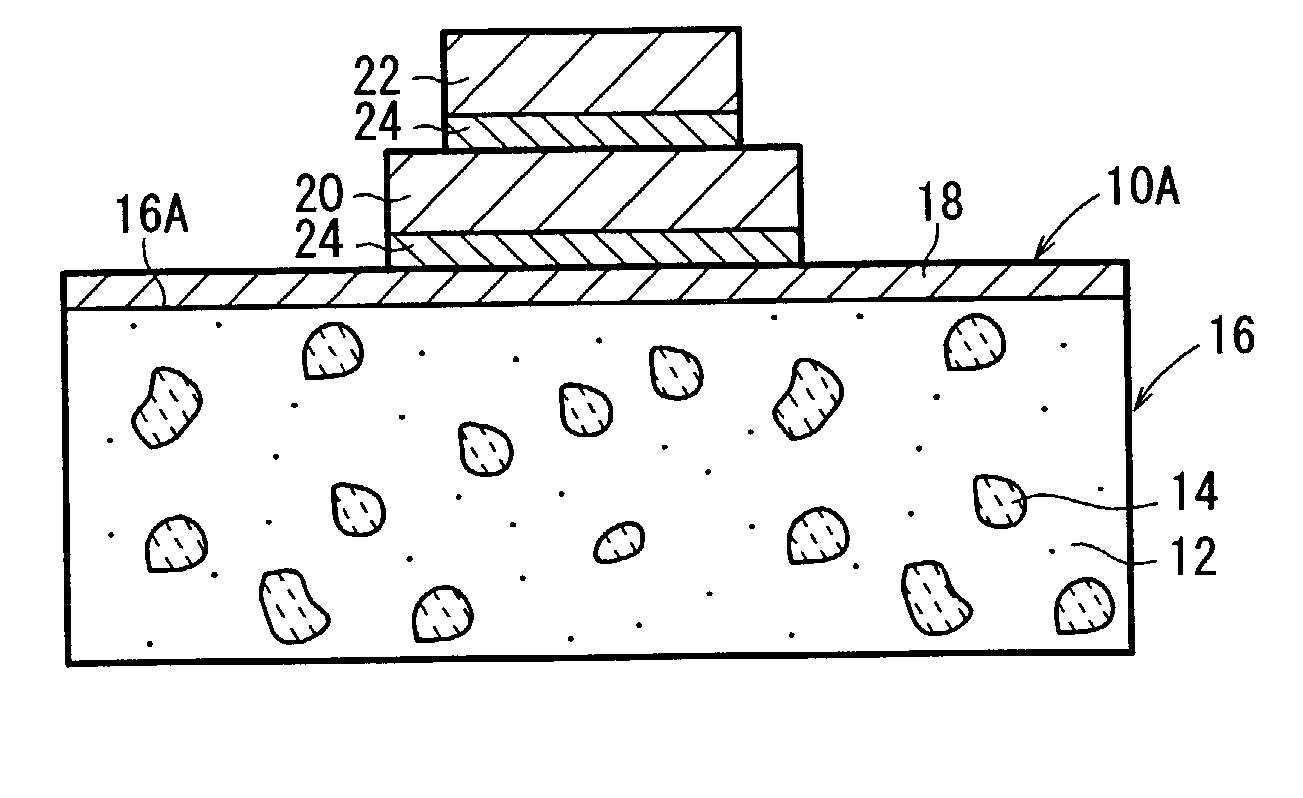
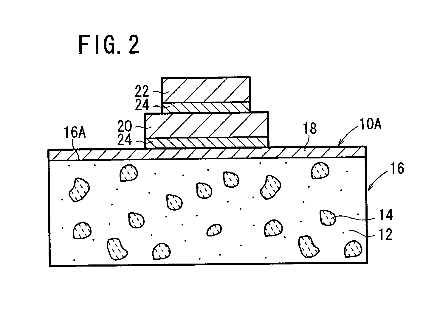
[0175] Example 2 concerning the first production method described above shows that a plating layer 18 of 20 .mu.m (NiP plating layer: 20 .mu.m) was formed on only the joining surface 16a of the composite raw material 16 by the electroplating treatment, followed by performing the drying treatment.

[0176] Example 3 concerning the second production method (or the production method concerning the modified embodiment) described above shows that a plating layer 18b of 1 .mu.m (NiP plating layer: 1 .mu.m) was formed on the both surfaces (or the entire surface) of the composite raw material 16 by the electroless plating treatment, followed by performing the drying treatment, and then a plating layer 18a of 19 .mu.m (NiP plating layer: 17 .mu.m, NiB plating layer: 2 .mu.m) was formed on only the joining surface 16a of the composite raw material 16 by the electroless plating treatment, followed by performing the drying treatment.

[0177] Example 4 shows that a plating layer 18b of 1 .mu.m (NiP p...


PUM

PropertyMeasurementUnit
thicknessaaaaaaaaaa
thicknessaaaaaaaaaa
thicknessaaaaaaaaaa

Abstract

A composite raw material is subjected to masking, and then the composite raw material is pretreated. After that, a surface of the composite raw material is activated, and a metal catalyst is applied to a joining surface of the composite raw material and a surface of a masking tape. Subsequently, an electroless plating treatment is performed to form a plating layer on the joining surface of the composite raw material and the surface of the masking tape. It is preferable that the thickness of the plating layer is 5 to 100 mum. After that, the masking tape which has been stuck to the composite raw material is removed, and then a drying treatment is performed for the composite raw material having the plating layer formed only on the joining surface.

Description

[0001] 1. Field of the Invention[0002] The present invention relates to a composite material which includes a composite raw material having a porous sintered body infiltrated with a metal and which is joined to another object by a junction layer. The present invention also relates to a method of producing the same.[0003] 2. Description of the Related Art[0004] Nowadays, it is not sufficient to consider only the coefficient of thermal conductivity for the constitutive material for the heat sink to be used, for example, IC chips which contain CPU's. It is necessary to select a material which has approximately the same coefficient of thermal expansion as those of silicon and GaAs of semiconductor substrates and which has a high coefficient of thermal conductivity.[0005] A variety of reports have been made in relation to the improvement of the heat sink material, including, for example, a case in which aluminum nitride (AlN) is used and a case in which Cu (copper)-W (tungsten) is used. ...

Claims


Application Information

Patent Timeline
Patent Type & Authority Applications(United States)
IPC IPC(8): C23C18/16C23C18/31C23C28/02C25D5/02C25D5/50C04B37/00C25D5/54C25D7/00H01L23/36H01L23/373
CPCC25D5/022C25D5/54H01L23/3733H01L23/3735C23C18/1889C23C18/1605Y10T428/12576C23C18/1651C23C18/1653H01L2924/0002C23C18/1644Y10T428/12535H01L2924/00C25D7/00
Inventor SUZUKI, KENISHIKAWA, SHUHEI
Owner NGK INSULATORS LTD
Why Eureka
Try Eureka