
Methods and arrangements in a radio communications system

a radio communication system and method technology, applied in the direction of synchronisation arrangement, synchronisation signal speed/phase control, site diversity, etc., can solve the problem of high capacity limits of cdma-based cellular systems, no solution to how these transmissions should be controlled, and documents that do not teach how to achieve synchronised communication between multiple base stations and a specific mobile station. , to achieve the effect of simple rake receivers, low average round-trip delays, and reduced complexity

Inactive Publication Date: 2002-09-10
TELEFON AB LM ERICSSON (PUBL)
View PDF11 Cites 121 Cited by
  • Summary
  • Abstract
  • Description
  • Claims
  • Application Information

AI Technical Summary

Benefits of technology

is to avoid having to rely on an external time reference receiver in each asynchronous base station in order to meet the synchronisation requirements during update of the active set for a mobile station.
As a consequence of the low buffering demand mobile stations can be made less complex and with simpler rake receivers.

Problems solved by technology

The capacity limits of CDMA-based cellular systems are high.
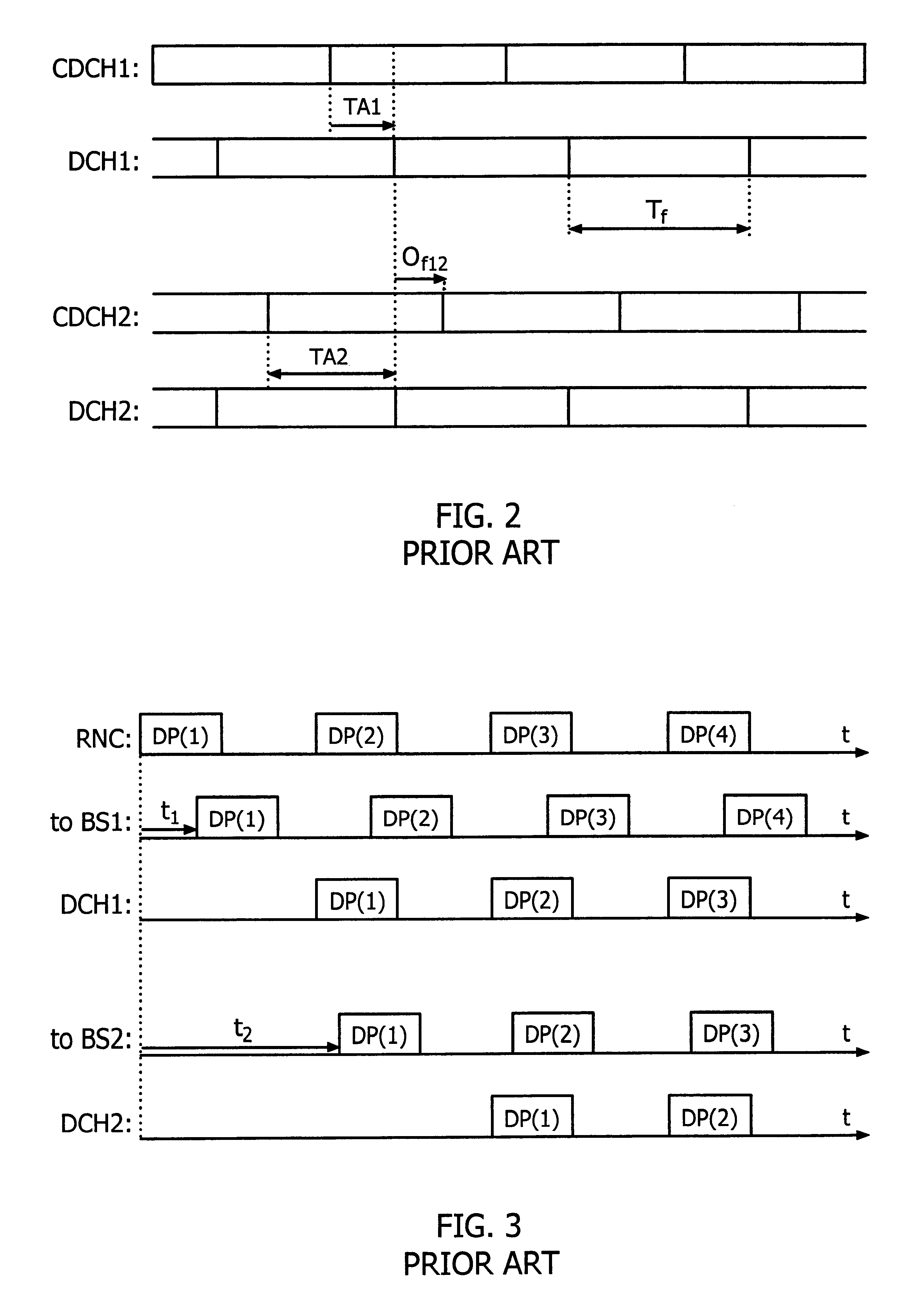
However, due to different propagation delays in the links, the signals arrive at different time instants at the mobile station.
However, the documents do not teach how to achieve synchronised communication between multiple base stations and a specific mobile station in spite of these delays.
Nevertheless, there is no solution to how these transmissions should be controlled when the delay differences between signals transmitted from different base stations exceed the duration of one half data frame.
Such small synchronisation errors result in low average round-trip delays in the system and allow the transport connections between the radio network control node and the base stations to be asynchronous, e.g. ATM connections.

Method used


Image

  • Methods and arrangements in a radio communications system
  • Methods and arrangements in a radio communications system
  • Methods and arrangements in a radio communications system

Examples


Embodiment Construction

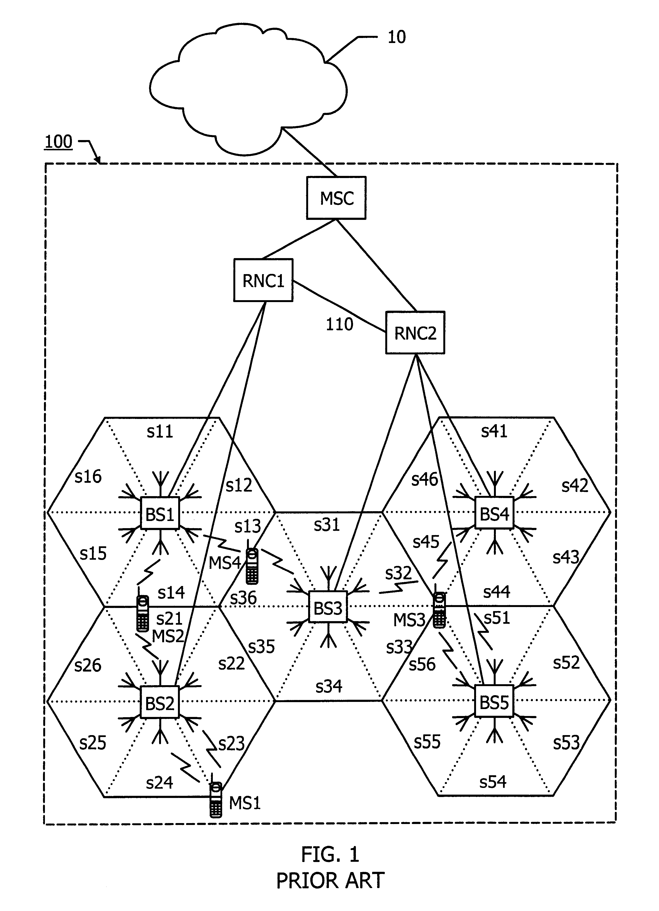
In FIG. 1 is shown a per se previously known CDMA cellular radio communications system 100 connected to a fixed communications network 10, like for instance the PSTN.

Naturally, the fixed communications network 10 can be any kind of network which is adapted to the type of data being transmitted through the CDMA cellular radio communications system 100. If, say, packet data is communicated in the CDMA system 100, the fixed network 10 is preferably a PSPDN (Packet Switched Public Data Network), a network operating according to IP (Internet Protocol), an ATM-network or a frame relay network.

A node MSC (Mobile services Switching Centre) connects the CDMA cellular radio communications system 100 with the fixed communications network 10. The node MSC may in particular be a so called Gateway Mobile services Switching Centre, if has connection with a communication network outside the CDMA cellular radio communications system 100. The node MSC is via, e.g. ATM-connections, in further contact ...


PUM


Abstract

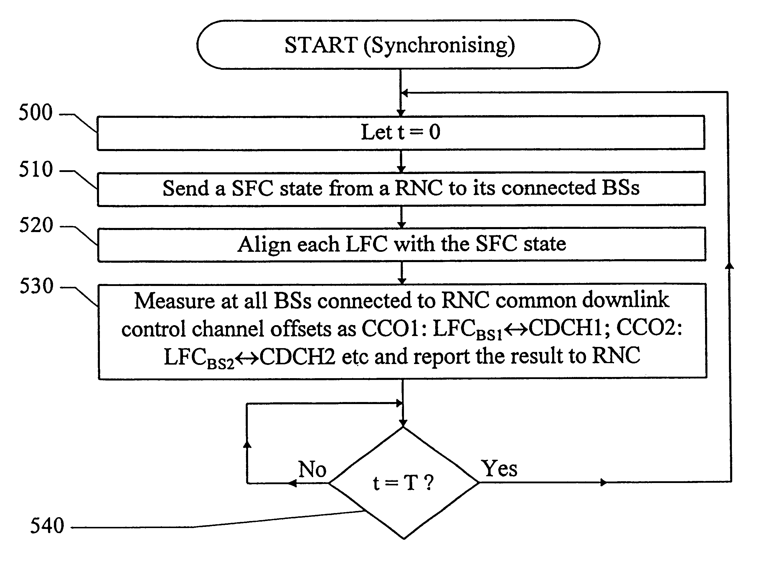
Methods and an arrangement for synchronizing communication of framed data via asynchronous base stations (BS1, BS2) in a cellular communication system are presented. The synchronization methods are performed continuously by sending out certain system frame counter states from a central node in the system to all its connected base stations (BS1, BS2). Each base station (BS1, BS2) includes a local frame counter (LFCBS1, LFCBS2), which generates local frame counter states (t1(1)-t1(4), t2(1)-t2(4)) correlated to the system frame counter states. Transmission of information via the base stations (BS1, BS2) is synchronized by assigning each data frame (DR(1)-DR(4)) a particular frame number, which is given by the local frame counter states (t1(1)-t1(4), t2(1)-t2(4)), so that data framed (DF(1)-DF(4)) having identical numbers contain copies of a certain data packet. Correct frame numbers are derived from common downlink channel offset measurements (CCO1, CCO2) carried out in the base stations (BS1, BS2), and timing advance values (TA2) and downlink channel offsets (DCO1, DCO2) calculated in the central node.

Description

The present invention relates to a method for synchronising communication of framed data via asynchronous base stations in a cellular communications system, e.g. a CDMA-system (Code Division Multiple Access). The synchronisation method is performed continuously, but in particular at connection establishment and during execution of soft handover.The invention is also directed to an arrangement for performing the above mentioned method.STATE OF THE ARTToday there is an increasing interest in using CDMA or spread spectrum systems in commercial applications. Some examples include digital cellular radio, land mobile radio, satellite systems, and indoor and outdoor personal communications networks referred to herein collectively as cellular systems.CDMA allows signals to overlap in both time and frequency. Thus, CDMA signals share the same frequency spectrum. In the frequency or the time domain, the multiple access signals appear to be on top of each other.There are a number of advantages...

Claims


Application Information

Patent Timeline
IPC IPC(8): H04B7/26H04J3/06H04J13/00H04L7/08H04W36/18H04W56/00
CPCH04B7/2668H04W36/18H04W56/0015H04B7/022H04B7/2684H04W56/00
Inventor WILLARS, PER HANS .ANG.KENASMAN, KARL ANDERS
Owner TELEFON AB LM ERICSSON (PUBL)
Learn More