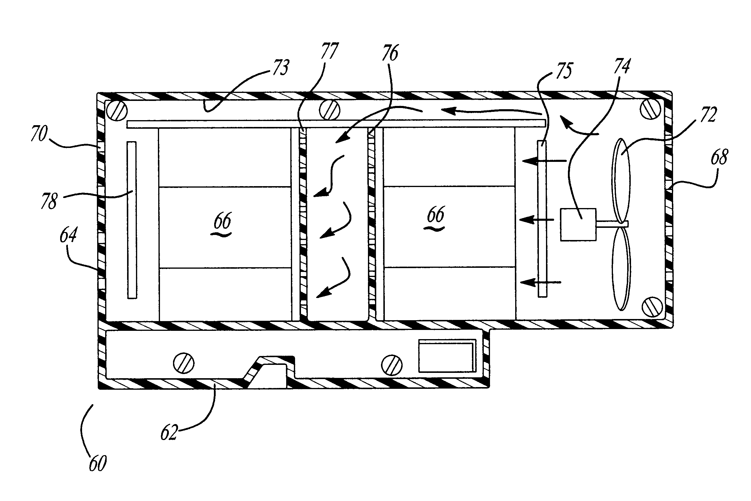
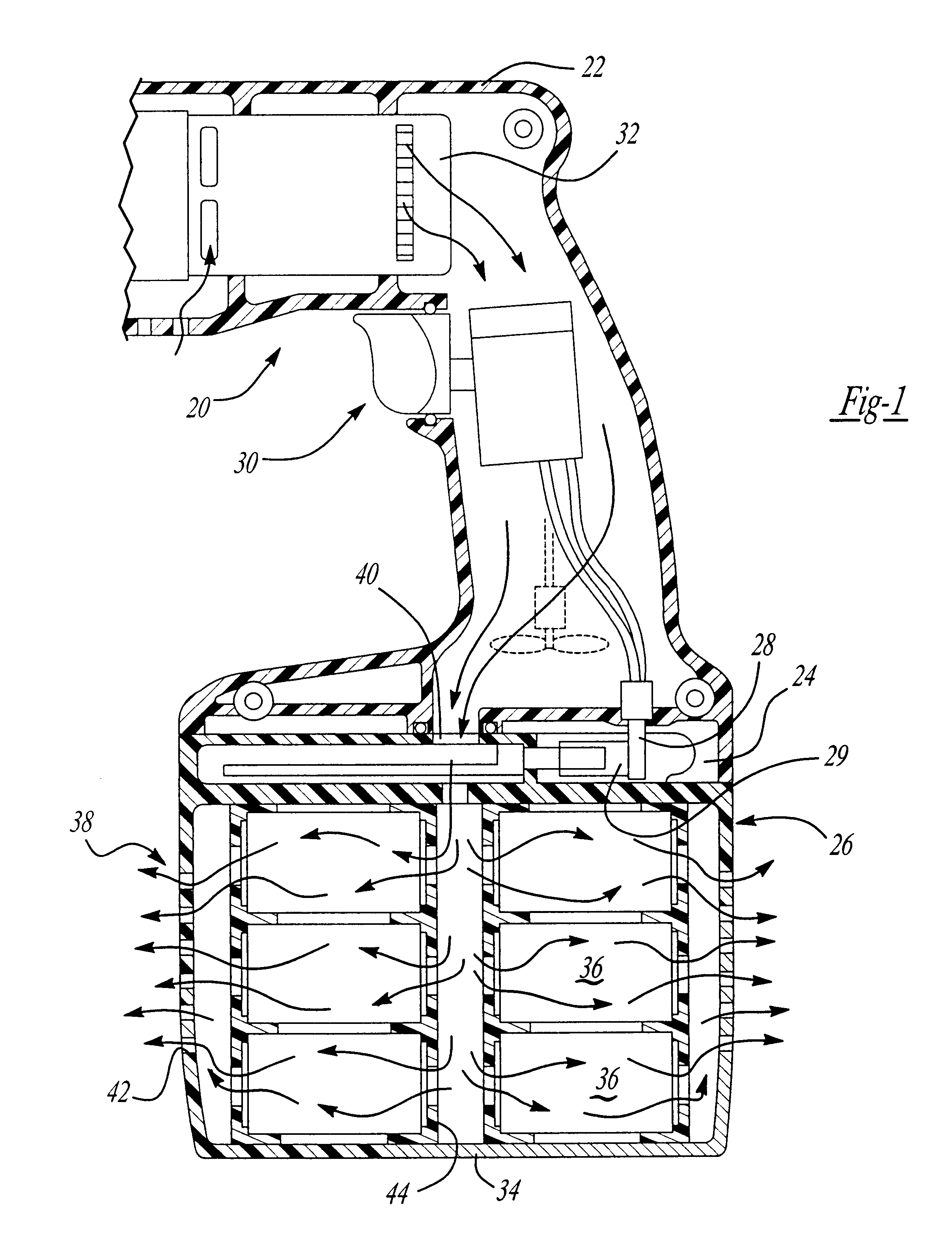
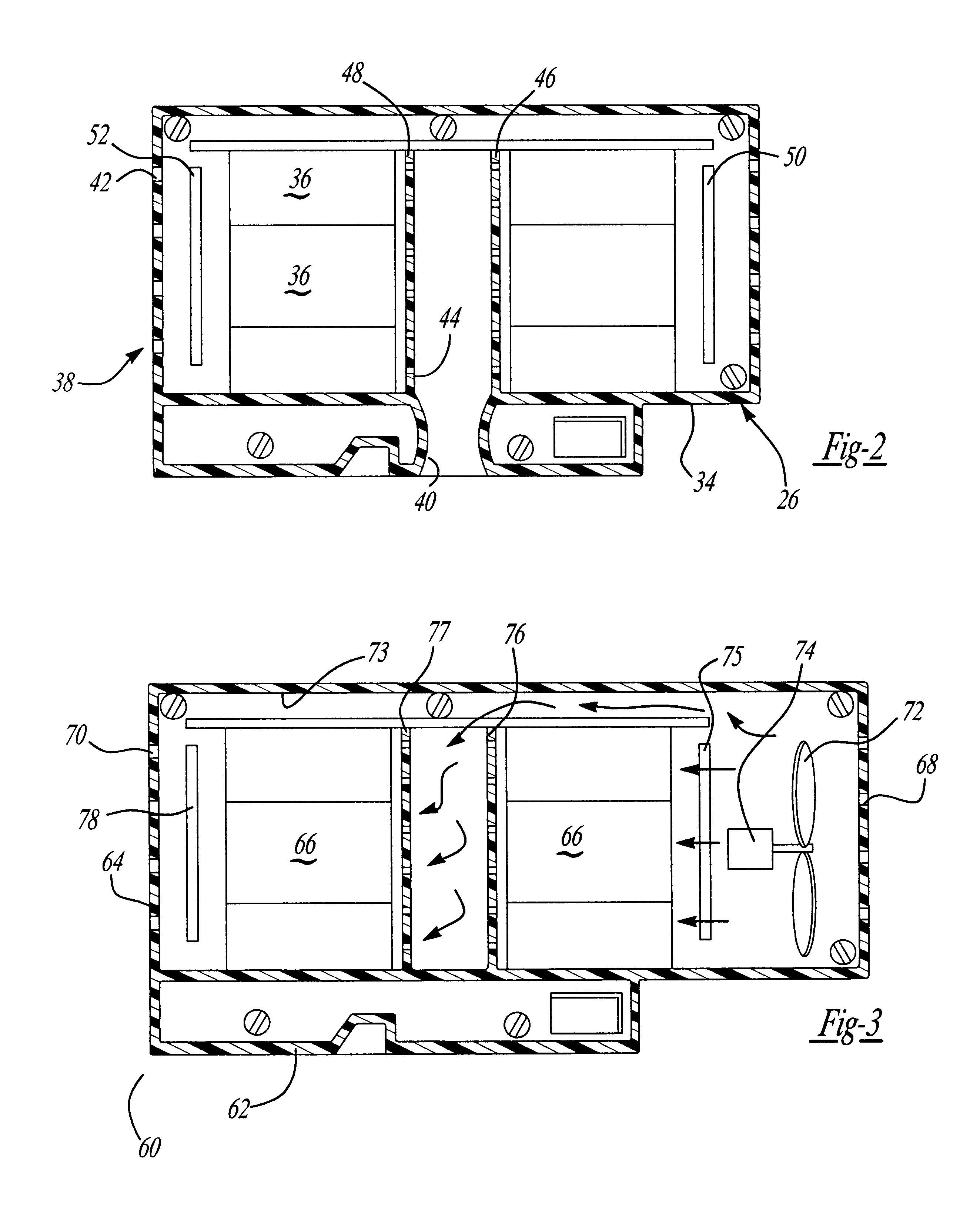
In accordance with a first aspect of the invention, a cordless
power tool to reduce charging time comprises a housing including a mechanism to couple a removable battery pack. A removable battery pack has a housing with one or more cells in the housing. A vent
system is in the housing to enable fluid passage through the housing. A mechanism is associated with the battery pack to dissipate heat in the battery pack housing. This heat removal from the battery pack reduces the battery pack charging time. The heat dissipating mechanism may include fluid directors to move fluid around cells as desired. Also, alternatively, a
heat sink may be used to dissipate heat from the cells. Further, alternatively, a fan may be used to force fluid through the vent
system to dissipate heat from the battery pack. The fan may be either in the tool housing or in the battery pack.
In accordance with a second aspect of the invention, a cordless
power tool to reduce charging time comprises a housing including a mechanism to couple with a removable battery pack. A removable battery pack has a housing with one or more cells in the housing. A vent system is in the housing to enable fluid passage through the housing. A mechanism is associated with the battery pack to dissipate heat from the battery pack. This heat removal from the battery pack reduces the battery pack charging time. The heat dissipating mechanism may include fluid directors to move fluid around the cells with higher temperatures. Further, alternatively, a
heat sink may be used to dissipate heat from the cells. Also, alternatively, a fan may be used to force fluid through the vent system to dissipate heat from the battery pack. The fan may be either in the tool housing or in the battery pack. A
battery charger to charge the battery pack is also included. The
battery charger has a mechanism to move fluid through the vent system of the battery pack housing. The charger may include a fan to force air through the battery pack vent system. Further, the battery pack may include a fan and in this case the charger may include a vent system to enable fluid to pass by the
cell or cells in the battery pack housing.
In accordance with a third aspect of the invention, a cordless power tool to reduce charging time comprises a housing including a mechanism to couple with a removable battery pack. A removable battery pack has a housing with one or more cells in the housing. A vent system is in the housing to enable fluid passage through the housing. A mechanism is associated with the battery pack to dissipate heat from the battery pack. This heat removal from the battery pack reduces the battery pack charging time. The heat dissipating mechanism may include fluid directors to move fluid around the battery cells. Also, alternatively, a
heat sink may be used to dissipate heat from the battery cells. Further, alternatively, a fan may be used to force fluid through the vent system to dissipate heat from the battery pack. The fan may be either in the tool housing or in the battery pack. Also, a battery charger to charge the battery pack is included. Here, an auxiliary fan is coupled with the charger or battery pack to force air through the charger or battery pack vent systems. The auxiliary fan is capable of moving fluid through the battery pack while the battery pack is secured with the charger.
In accordance with a fourth aspect of the invention, a cordless power tool to reduce charging time comprises a housing including a mechanism to couple with removable battery pack. A removable battery pack has a housing with one or more cells in the housing. A vent system is in the housing to enable fluid passage through the housing. A mechanism is associated with the battery pack to dissipate heat from the battery pack housing. This heat removal from the battery pack reduces the battery pack charging time. The heat dissipating mechanism may include fluid directors to move fluid around the battery cells. Also, alternatively, a heat sink may be used to dissipate heat from the battery cells. Further, alternatively, a fan may be used to force fluid through the vent system to dissipate heat from the battery pack. The fan may be either in the tool housing or in the battery pack. A
heat pump is included to provide heating or cooling of the battery cells depending upon the temperature of the battery cells. Thus, the
heat pump enables the battery cells to be cooled if they are above a desired temperature and to be heated if the cells are below a desired temperature to enable charging of the cells.
In accordance with a fifth aspect of the invention, a cordless power tool to reduce charging time comprises a housing including a mechanism to couple with a removable battery pack. A removable battery pack has a housing with a plurality of cells in the housing. A vent system is in the housing to enable fluid passage through the housing. A mechanism is associated with the battery pack to dissipate heat or equalize temperatures in the battery pack. The heat removal from the battery pack reduces the battery pack charging time. The heat dissipating mechanism may include fluid directors to move fluid around the cells with higher temperatures. Also, alternatively, a heat sink may be used to dissipate heat from the higher temperature cells. Further, alternatively, a fan may be used to force fluid through the vent system to dissipate heat from the battery pack. The fan may be either in the tool housing or in the battery pack. A sensing mechanism may be included to sense the temperature of the plurality of cells in the battery pack housing. The heat dissipator equalizes the temperature of the plurality of cells. The heat dissipator wicks heat from the hotter cells to ambient or to the other cells to equalize
cell temperature within the housing.
In accordance with a sixth aspect of the invention, a removable battery pack has a housing with one or more cells in the housing. A vent system is in the housing to enable fluid passage through the housing. A mechanism is associated with the battery pack to dissipate heat from the battery pack. This heat removal from the battery pack reduces the battery pack charging time. The heat dissipating mechanism may include fluid directors to move fluid around cells. Also, alternatively, a heat sink may be used to dissipate heat from the cells. Further, alternatively, a fan may be used to force fluid through the vent system to dissipate heat from the battery pack. The fan may be either in the tool housing or in the battery pack.


