Encapsulated antenna in passive transponders

a passive transponder and antenna technology, applied in the field of passive transponders, can solve the problems of air space, inability to return search equipment in practice, and sensitive to the environment of the antenna, and achieve the effect of reducing the influence of the antenna's surroundings

Inactive Publication Date: 2002-09-24
RECCO INVEST
View PDF8 Cites 61 Cited by
  • Summary
  • Abstract
  • Description
  • Claims
  • Application Information

AI Technical Summary

Benefits of technology

is to provide a transponder that provides an optimum yield of the RF energy received on the base frequency and the RF energy retransmitted on a first harmonic of the base frequency.
The advantage that is achieved with the invention is that the near field of the antenna is substantially not, or only to a small degree, influenced by the surroundings of the antenna.
Another advantage which is achieved with the invention is that the dielectric which surrounds the transponder concentrates the RF-energy to a transmission line whereby the influence of the surroundings on the transponder's characteristics are reduced.
Finally, none of the US patents discussed above discloses a dielectric material surrounding the antenna so as to reduce the influence the antenna's surroundings on the near-field of the antenna.

Problems solved by technology

So long that in practice it is inappropriate to have an air space between the transponder and the human body.
The applicant has found that a problem occurs if the transponder is mounted in a ski boot made of plastic.
Returning of the search equipment is not possible in practice.
A drawback with the transponders of the first two US patents mentioned is that they are sensitive to the environment of the antenna.
None of the US patents above discloses a matching network for matching the impedance of the passive component to the impedance of the antenna.
In particular none of the US patents disclose an impedance matching transmission line.
Furthermore, none of the US patents above discloses a dielectric material surrounding the transmission line so as to concentrate the energy transported by the transmission line to the transmission line itself, thereby making the transmission line generally independent of the surroundings of the transponder.
Finally, none of the US patents discussed above discloses a dielectric material surrounding the antenna so as to reduce the influence the antenna's surroundings on the near-field of the antenna.

Method used


Image

  • Encapsulated antenna in passive transponders
  • Encapsulated antenna in passive transponders
  • Encapsulated antenna in passive transponders

Examples


Embodiment Construction

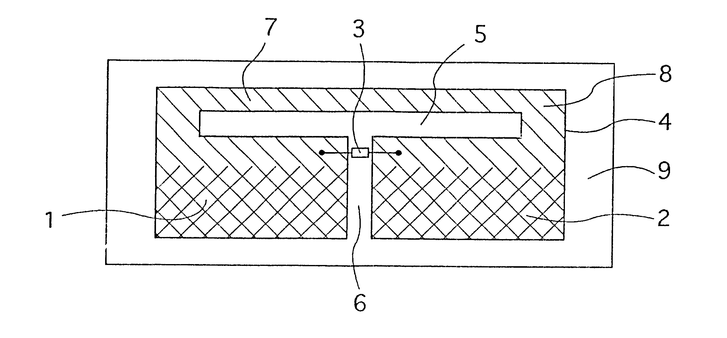
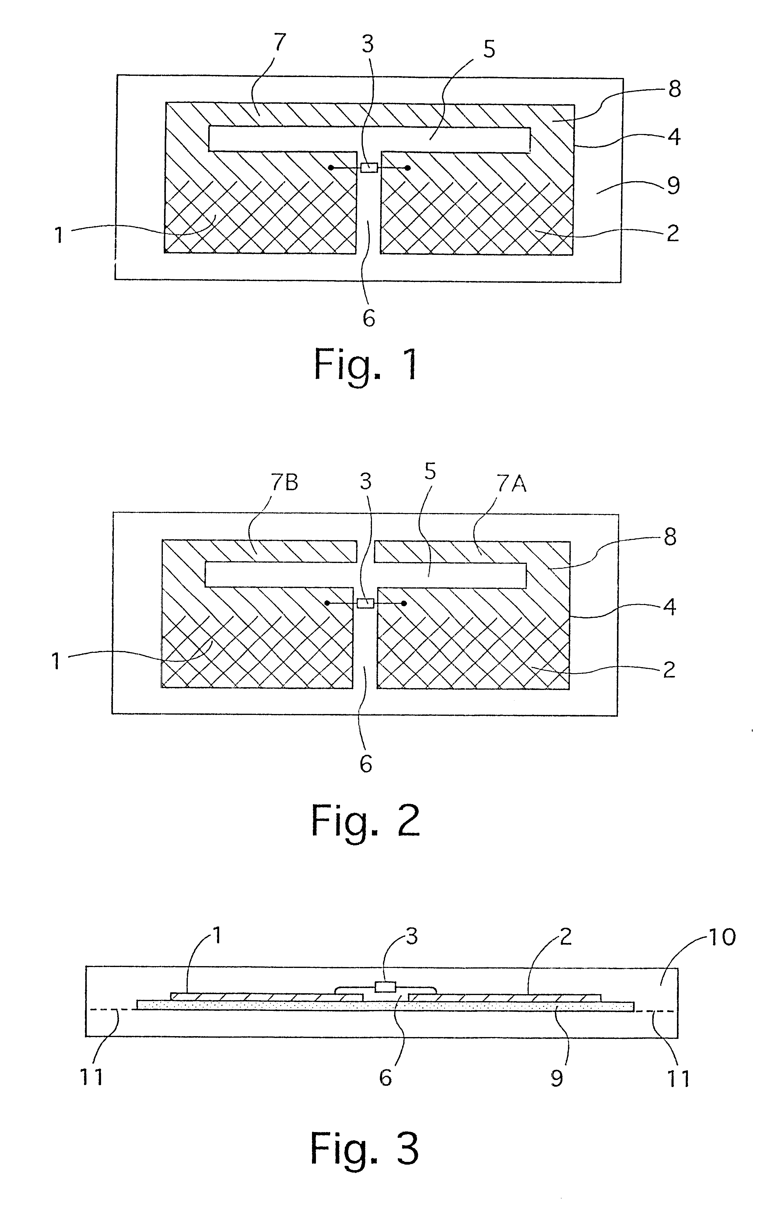
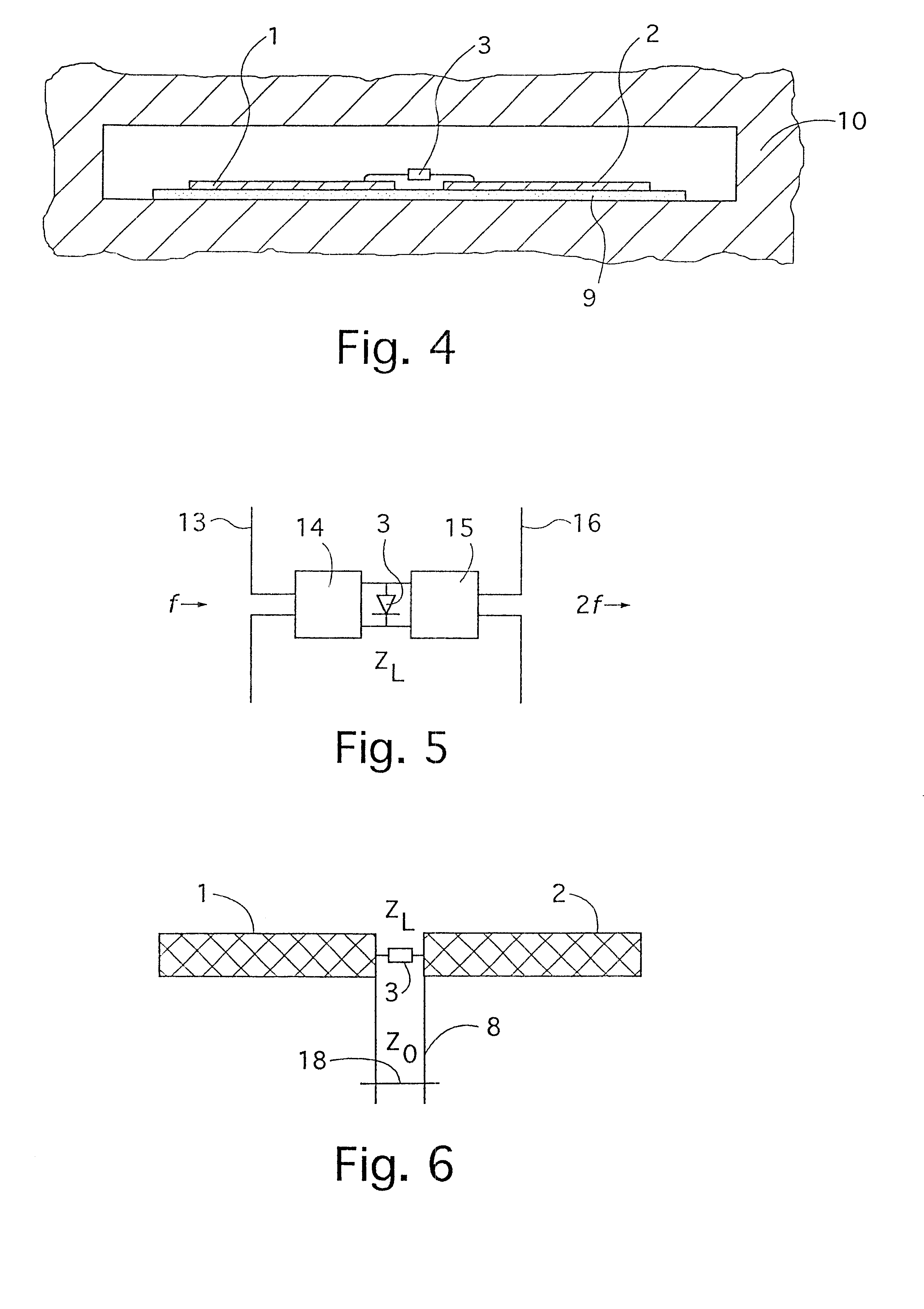
FIG. 1 shows a transponder with antenna elements 1, 2 and a diode 3. The antenna elements 1, 2 form an antenna, which in this embodiment is manufactured from a metal foil 4. The metal foil has a T-shaped slot with a horizontal section 5 and a vertical section 6. The diode is situated over the vertical section 6 of the slot. The T-shaped slot divides the metal foil into two main surfaces joined to each other by a supplementary surface 7. The antenna element 1 is a part of one of the main surfaces, the antenna element 2 is a part of the other main surface. The other parts of the respective main parts together form with the supplementary surface a transmission line 8 which in this embodiment of the transponder is short-circuited.

The transmission line is shown with single crosshatching, the antenna elements with double crosshatching. The transition region between the antenna elements and the transmission line is not as sharp as shown in the figures. The diode 3 is soldered between the a...


PUM


Abstract

A passive transponder comprises an antenna (1, 2) in the form of a metal body with two main surfaces and a diode (3) connected between the main surfaces and a dielectric (10) surrounding the antenna. A characteristic of the invention is that the impedance of the antenna is adapted to the impedance of the diode by matching unit (13, 14). A transmission line (8) is used as the matching unit. Another characteristic for the invention is that the transmission line is surrounded by a dielectric (10) made of plastic. Yet another characteristic of the invention is that the antenna is surrounded by a dielectric made of plastic which reduces the influence of the surroundings on the near field of the antenna.

Description

The invention relates in general to a passive transponder used for the localization of people and of objects with the help of a radio transmitter which transmits RF-energy on one frequency and with the help of a radio receiver which receives RF-energy retransmitted on another frequency by the transponder.STATE OF THE ARTU.S. Pat. No. 4,331,957 describes a passive transponder used for the rescuing of skiers who have been caught in avalanches. The transponder is glued onto a ski boot. The transponder includes an antenna in the shape of a metal foil with two main surfaces and a diode connected between the main surfaces. A mobile radio transmitter with a thereto-connected directional antenna emits radio frequency energy on a base frequency of 915 MHz. A mobile radio receiver, built together with the radio transmitter, is tuned to double the base frequency, 1830 MHz, and is connected to the directional antenna. The signal from the transmitter is modulated with an audio frequency within t...

Claims


Application Information

Patent Timeline
Patent Type & Authority Patents(United States)
IPC IPC(8): H01Q13/10H01Q1/22H01Q1/38G01S13/75H01Q1/40G01S13/76G01S13/79H01P5/08H01Q9/16H04B1/59H04B5/02
CPCH01Q1/22H01Q1/2225H01Q1/38H01Q13/106
Inventor GRANHED, MAGNUSFUKS, PETERLARSSON, GUNNARREHN, ANDERS
Owner RECCO INVEST
Why Eureka
Try Eureka