AI technical title is built by Patsnap AI team. It summarizes the technical point description of the patent document.
a technology of illumination apparatus and illumination efficiency, which is applied in the direction of projectors, color television details, instruments, etc., can solve the problems of reducing illumination efficiency, reducing illumination efficiency, and not increasing illumination efficiency so much
Inactive Publication Date: 2002-10-15
CANON KK
View PDF7 Cites 39 Cited by
Summary
Abstract
Description
Claims
Application Information
AI Technical Summary
This helps you quickly interpret patents by identifying the three key elements:
Problems solved by technology
Method used
Benefits of technology
Problems solved by technology
For these reasons, the conventional example described in the aforementioned official gazette employed the ellipsoidal mirror and the concave lens (negative lens) in the light source section in order to improve the illumination efficiency, but optimization of the shape of the concave lens was not enough, though the size reduction of the lens arrays was realized to some extent; therefore, it had the problem that the illumination efficiency was not increased so much.
In the region below the lower limit of Condition (2), the exit diameter of beams from the light source section becomes small, but the parallelism of beams is too poor, so as to decrease the illumination efficiency.
In the region over the upper limit of Condition (2), the exit diameter of beams from the light source section is too large, so that a great eclipse occurs at the entrance pupil of the projection lens, thereby decreasing the illumination efficiency.
In the region below the lower limit of Condition (3), the exit diameter of beams from the light source section becomes small, while the parallelism of beams becomes too poor, so as to decrease the illumination efficiency.
In the region over the upper limit of Condition (3), the exit diameter of beams from the light source section becomes too large and a large eclipse appears at the entrance pupil of the projection lens, thus decreasing the illumination efficiency.
It thus results in degrading the parallelism and in turn increasing the eclipse at the shield plates of the polarization converting element.
Method used
Image
Click on the blue label to locate the original text in one second.
Reading with bidirectional positioning of images and text.
Examples
numerical example 2 (corresponding to the light source section of fig.6)
Numerical Example 2 (corresponding to the light source section of FIG. 6)
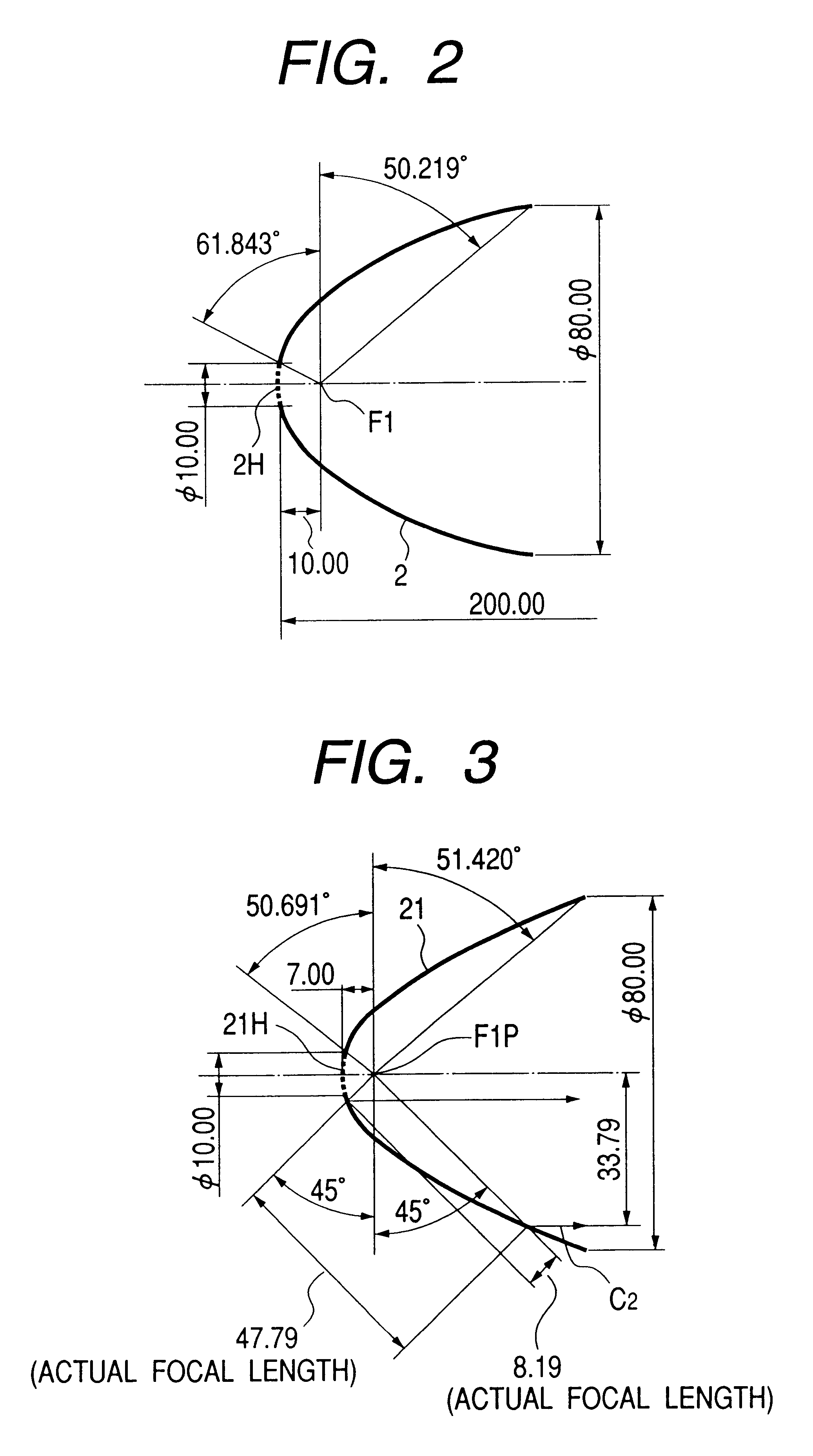
Ellipsoidal mirror F1: 10 mm, F2: 200 mm
Concave lens R1: 95.2 mm, R2: 40 mm, D: 2 mm, K: aspherical coefficient of R2 (K=-0.5), N: 1.51633
Distance between the vertex of the reflecting surface of the ellipsoidal mirror and the concave lens R1: 72 mm
numerical example 3 (corresponding to the light source section of fig.7)
Numerical Example 3 (corresponding to the light source section of FIG. 7)
Ellipsoidal mirror F1: 10 mm, F2: 200 mm
Concave lens R1: 71 mm, R2: 35 mm, D: 2 mm, K: aspherical coefficient of R2 (K=-0.5), N: 1.51633
Distance between the vertex of the reflecting surface of the ellipsoidal mirror and the concave lens R1: 72 mm
numerical example 4 (corresponding to the light source section of fig.8)
Numerical Example 4 (corresponding to the light source section of FIG. 8)
Ellipsoidal mirror F1: 10 mm, F2: 180 mm
Concave lens R1: 71 mm, R2: 35 mm, D: 2 mm, K: aspherical coefficient of R2 (K=-0.5), N: 1.51633
Distance between the vertex of the reflecting surface of the ellipsoidal mirror and the concave lens R1: 52 mm
PUM
Property
Measurement
Unit
size
aaaaa
aaaaa
diameter
aaaaa
aaaaa
diameter
aaaaa
aaaaa
Abstract
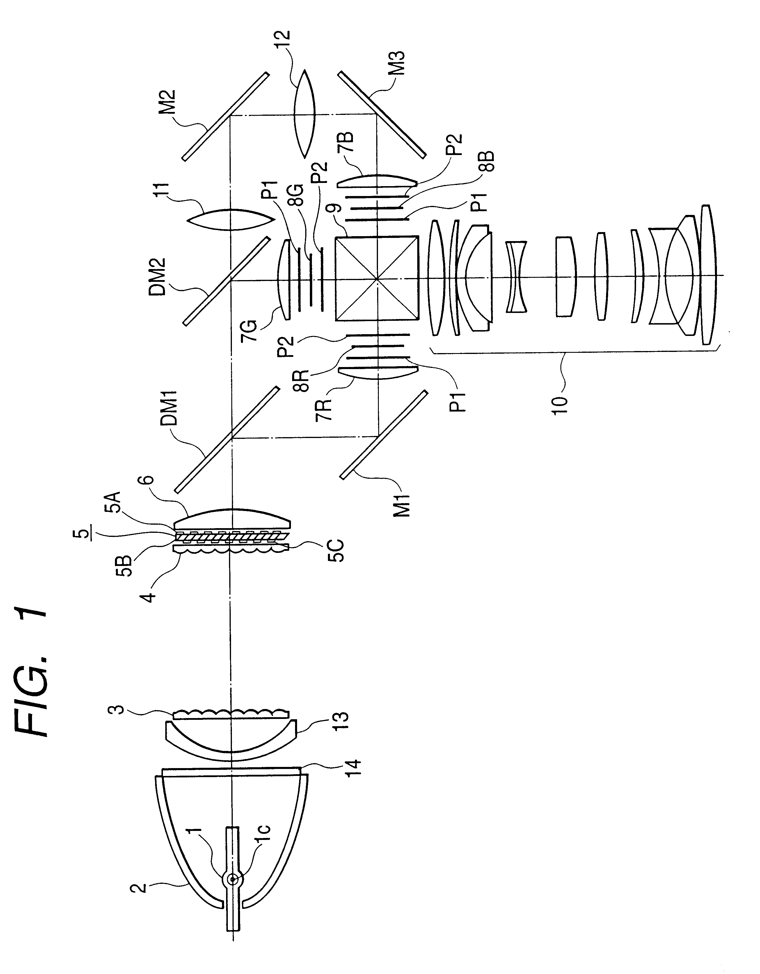
For increasing the illumination efficiency to a liquid-crystal display element, an illuminating apparatus has a reflector for reflecting light from a light source, a negative meniscus lens, which is convex on the light source side, a first lens array unit of lens elements, a second lens array unit of lens elements, which is conjugate with the light source, and an optical polarization converting element in the stated order along a traveling direction of the light from the light source. The illuminating apparatus illuminates the liquid-crystal display element through the optical polarization converting element.
Description
1. Field of the InventionThe present invention relates to an illuminating apparatus used in liquid-crystal projectors etc., and a projection type display apparatus using it.2. Related Background ArtThe conventional illuminating devices for projection type display apparatus were usually constructed of a combination of arc tube 1 with parabolic mirror 19 as illustrated in FIG. 10.In FIG. 10, white light emitted from a light-emitting portion 1c of the arc tube 1 (light source) is converted into nearly parallel light by the parabolic mirror 19 and a first lens array 3 forms a light source image of the arc tube 1 at the center of each lens of second lens array 4. The first lens array 3 and the second lens array 4 have their respective focal lengths approximately equal to each other, and the first lens array 3 and the second lens array 4 are spaced from each other so that the spacing between them is approximately equal to the focal length of the first lens array 3.The light condensed by t...
Claims
Application Information
Patent Timeline
Application Date:The date an application was filed.
Publication Date:The date a patent or application was officially published.
First Publication Date:The earliest publication date of a patent with the same application number.
Issue Date:Publication date of the patent grant document.
PCT Entry Date:The Entry date of PCT National Phase.
Estimated Expiry Date:The statutory expiry date of a patent right according to the Patent Law, and it is the longest term of protection that the patent right can achieve without the termination of the patent right due to other reasons(Term extension factor has been taken into account ).
Invalid Date:Actual expiry date is based on effective date or publication date of legal transaction data of invalid patent.

