

Time measurement device
- Summary
- Abstract
- Description
- Claims
- Application Information
AI Technical Summary
Benefits of technology
Problems solved by technology
Method used
Image

Examples
Embodiment Construction
Referring to the drawings, preferred embodiments of the present invention are discussed.
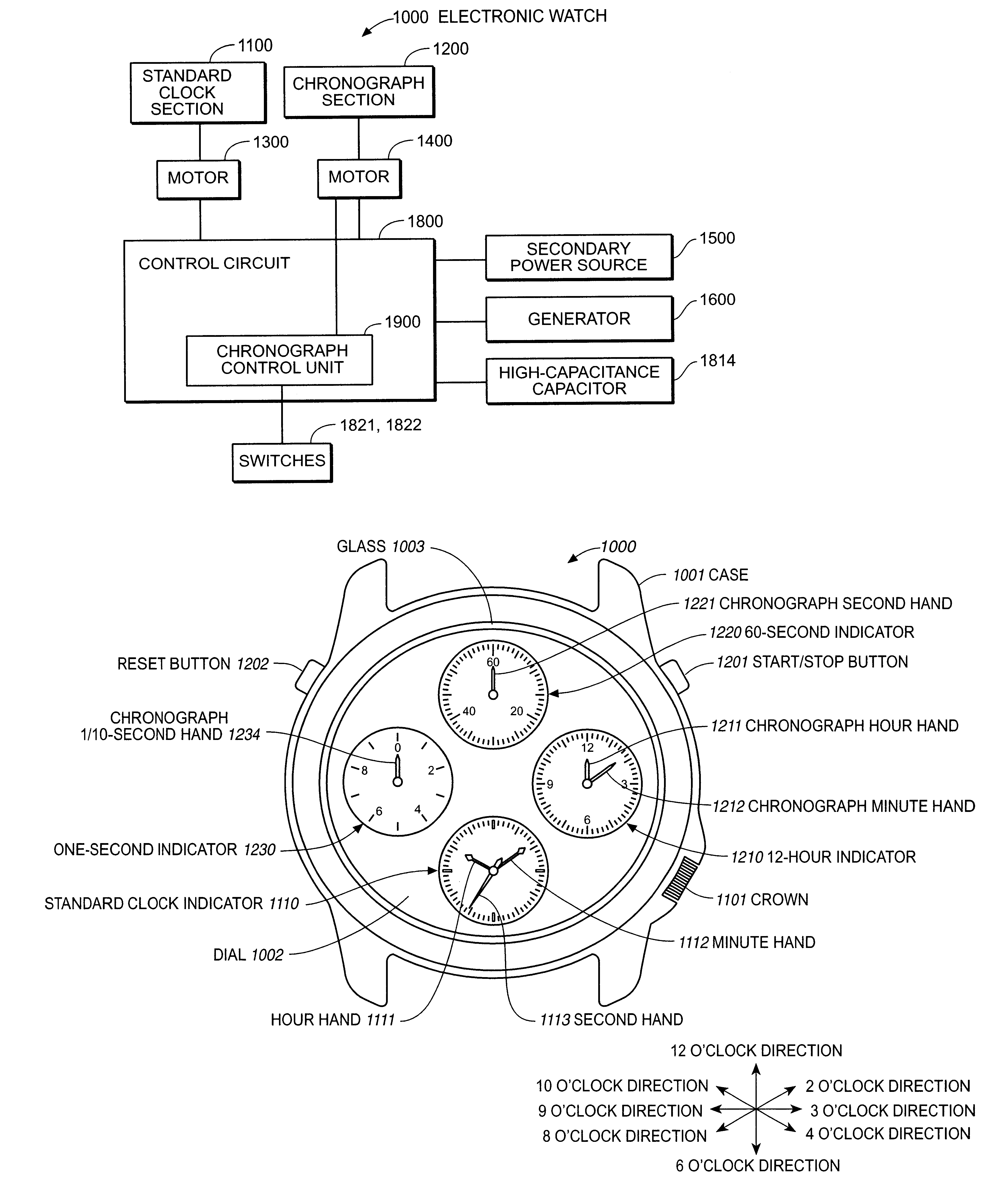
FIG. 1 is a block diagram showing one embodiment of an electronic watch as a time measurement device of the present invention.
The electronic watch 1000 includes two motors 1300 and 1400 for respectively driving a standard clock section 1100 and a chronograph section 1200, a high-capacitance capacitor 1814, as a first power source unit, and a secondary power source 1500, as a second power source unit, for feeding power to drive the motors 1300 and 1400, a generator 1600 for charging the secondary power source 1500, and a control circuit 1800 for generally controlling the electronic watch 1000. The control circuit 1800 includes a chronograph control unit 1900 having switches 1821 and 1822 for controlling the chronograph section 1200 in a method to be described later. The secondary power source 1500 and the high-capacitance capacitor 1814 function as a power source for the electronic watch 1000. Bes...
PUM
 Abstract
Description
Claims
Application Information