Microgyroscope with two resonant plates

a gyroscope and resonant plate technology, applied in the direction of acceleration measurement using interia force, turn-sensitive devices, instruments, etc., can solve the problems of bad influence on the sensitivity of the gyroscope, the difference in the resonance frequency of the two resonant plates, and the difficulty in separating an acceleration signal from a signal

Inactive Publication Date: 2002-10-22
SAMSUNG ELECTRONICS CO LTD
View PDF5 Cites 24 Cited by
  • Summary
  • Abstract
  • Description
  • Claims
  • Application Information

AI Technical Summary

Benefits of technology

It is a second object of the present invention to provide a microgyroscope with two resonant plates allowing an error in manufacturing to be reduced, thereby increasing reproducibility and yields.
It is a third object of the present invention to provide a microgyroscope with two resonant plates which can protect a mode coupling effect due to the interference between a driving mode and a sensing mode.
It is a fourth object of the present invention to provide a microgyroscope with two resonant plates which maintains high stability against thermal stress.

Problems solved by technology

In such conventional resonant type gyroscopes having two resonant plates, the thicknesses or weights of springs supporting the two resonant plates may differ due to, for example, a process error occurring during patterning for a vibratory structure, thereby causing the resonance frequencies of the two resonant plates to be different.
Here, even the several Hz of difference between the resonance frequencies of the two resonant plates has a bad influence on the sensitivity of a gyroscope.
However, in such a gyroscope, it is very difficult to separate an acceleration signal from a signal because the influence of acceleration cannot be removed from such a structure having a single resonant plate.
However, such method and meter creates interference between components in different directions (cross-axis sensitivity).
When a spring employing a bending mode is applied to a thick structure in order to detect the displacement in the direction perpendicular to a substrate, an error in the thickness of the spring causes a large variation in the spring constant.
Thus, reproducibility of processes cannot be guaranteed.
However, since a torsion mode spring is short, thermal stress caused by transformation due to a change in temperature is concentrated on the spring, and thus the structure linked to the spring easily becomes unstable.
However, in conventional resonant type gyroscopes including a gyroscope disclosed in U.S. Pat. No. 5,892,153 which embody a spring used in a driving mode and a spring used in a sensing mode in a single spring structure, an abnormal mode may take place due to, for example, large transformation of the spring.
Due to such an abnormal mode, it is difficult to adjust the difference between a sensing frequency and a driving frequency to be 100 Hz or lower.

Method used


Image

  • Microgyroscope with two resonant plates
  • Microgyroscope with two resonant plates
  • Microgyroscope with two resonant plates

Examples


Embodiment Construction

Hereinafter, embodiments of a microgyroscope according to the present invention will be described in detail with reference to the attached drawings.

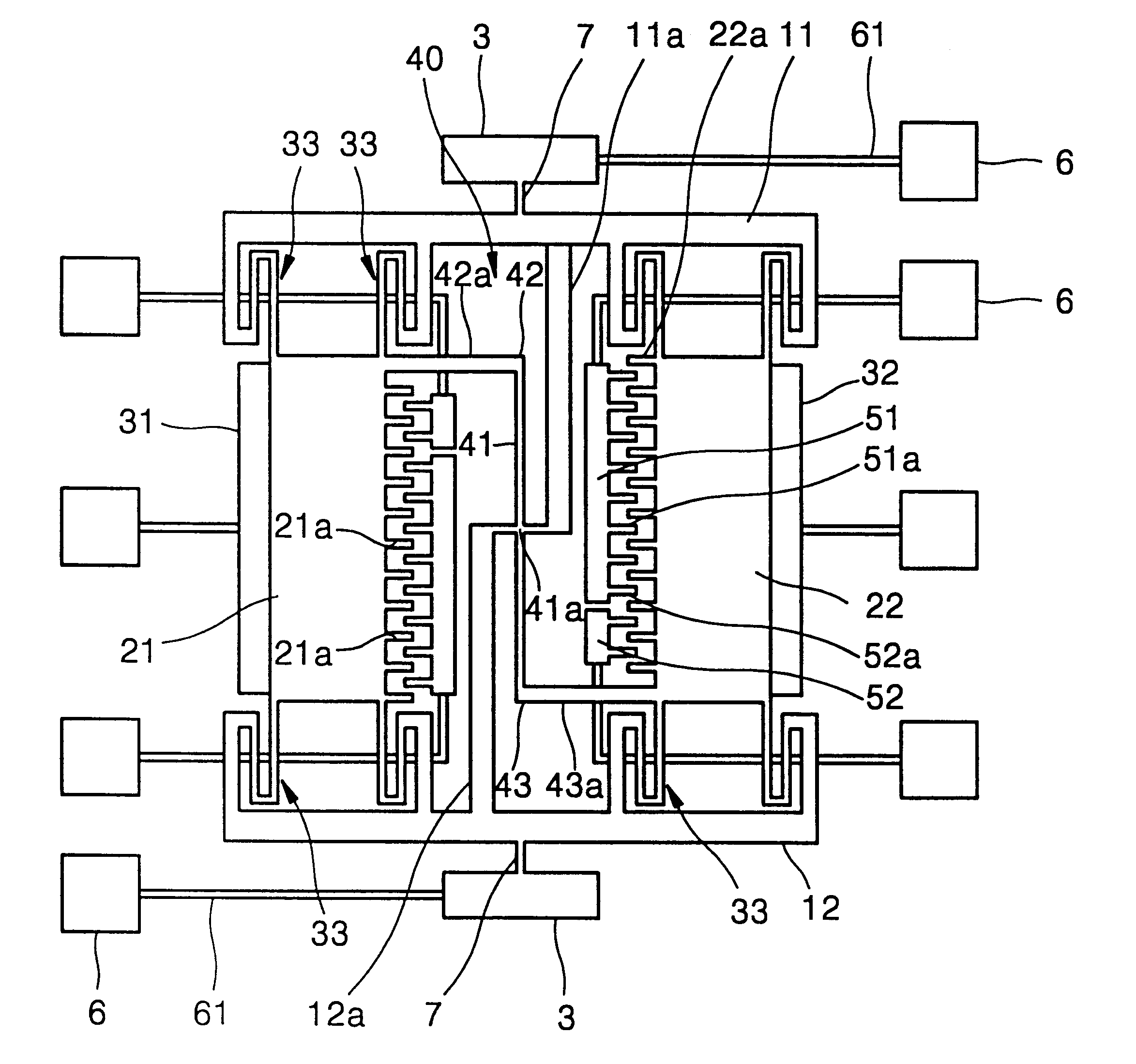
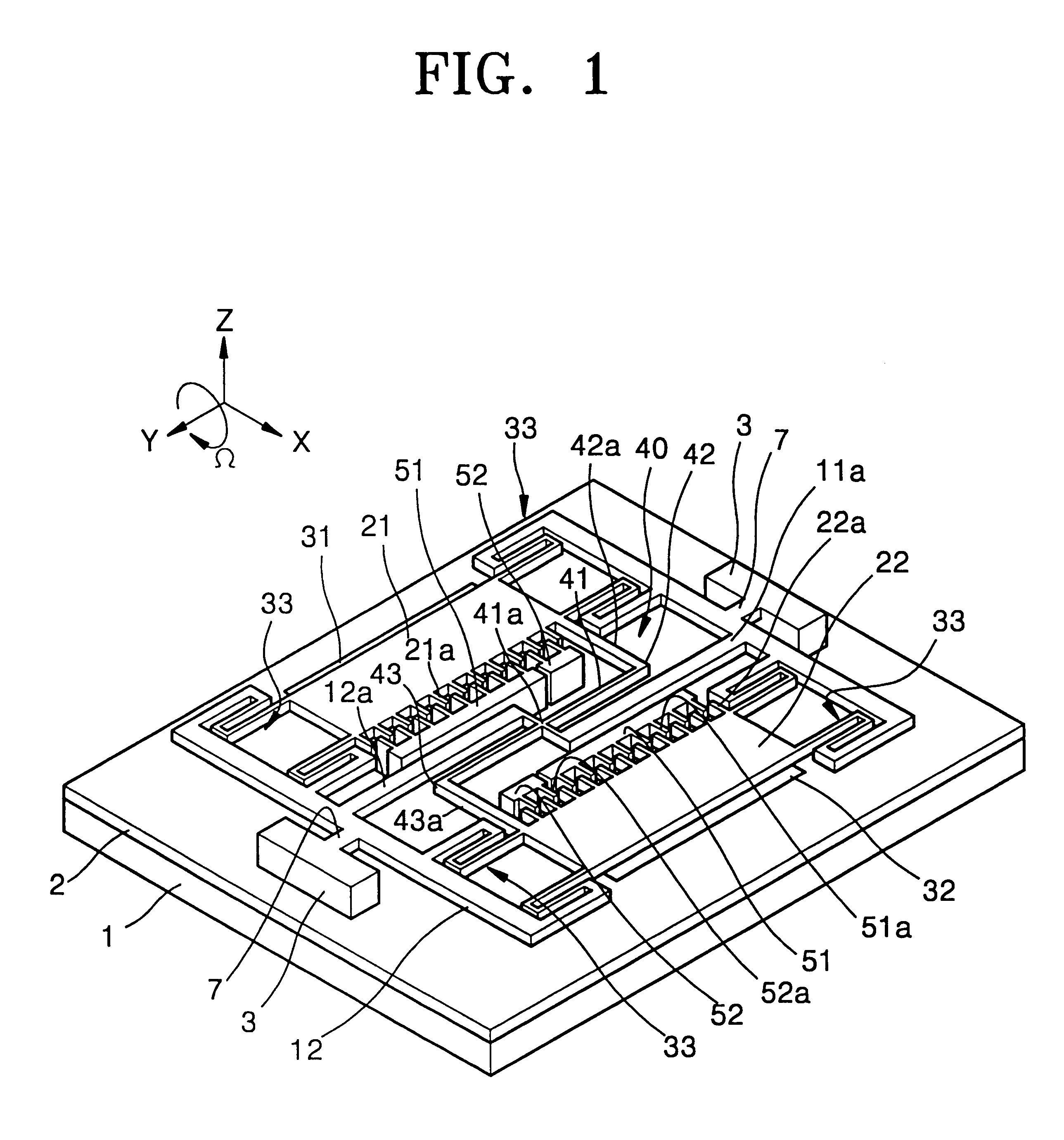
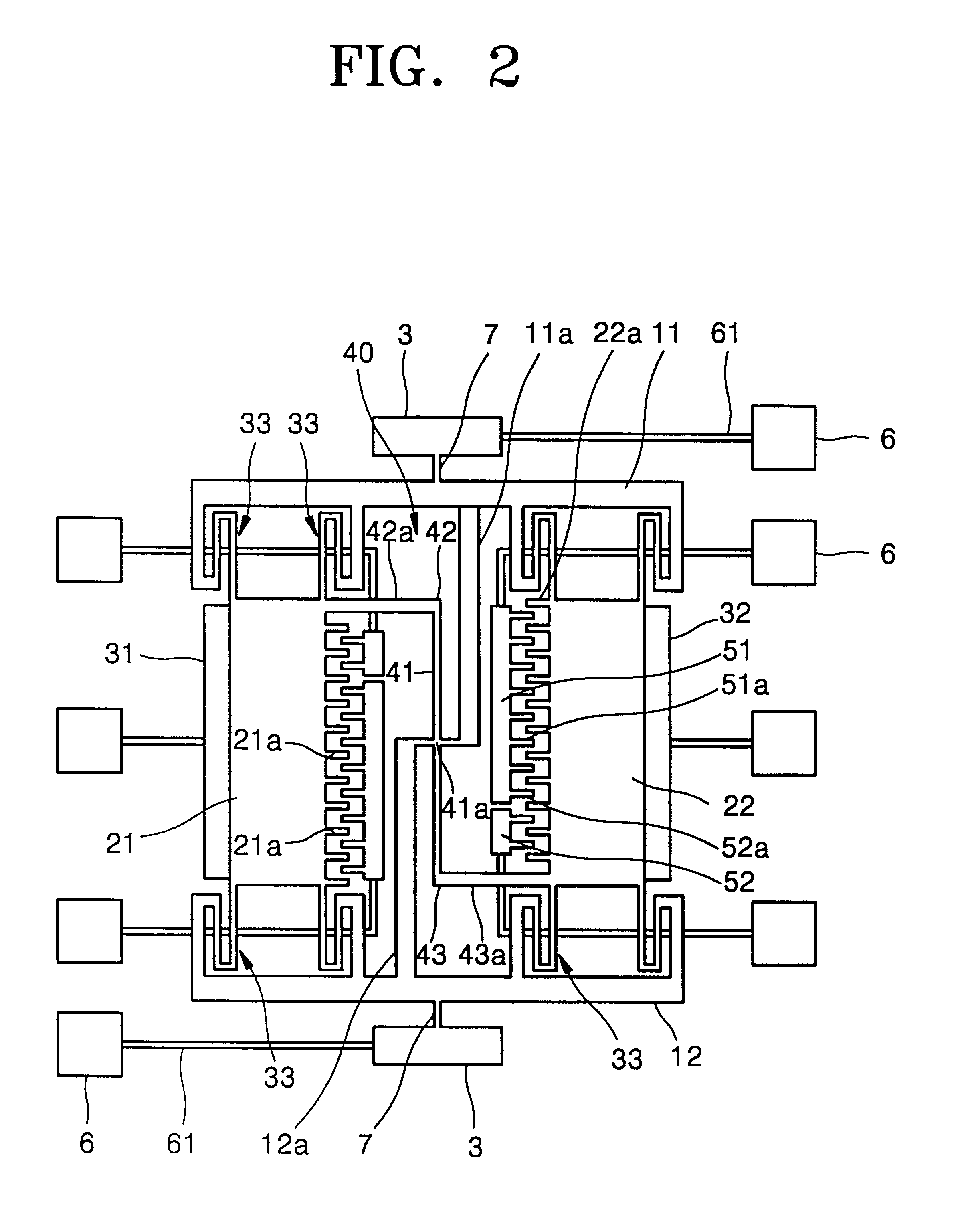
FIG. 1 is a schematic perspective view illustrating an embodiment of a microgyroscope according to the present invention. FIG. 2 is a plan view illustrating the layout of the overall structure of the embodiment of the microgyroscope of FIG. 1.

Referring to FIGS. 1 and 2, an insulation layer 2 is formed on a substrate 1, and a resonance structure is formed above the insulation layer 2. The resonance structure includes first and second frames 11 and 12 which are supported by anchors 3 to be parallel to each other and first and second resonant plates 21 and 22 between the first and second frames 11 and 12.

A sensing beam 7 is provided between each of the first and second frames 11 and 12 and a corresponding anchor 3. The sensing beams 7 serve as torsion springs with respect to the motion of the first and second frames 11 and 12.

The first and ...


PUM


Abstract

A microgyroscope with two resonant plates is provided. The microgyroscope includes a substrate; first and second frames provided on the substrate to have a predetermined height, the first and second frames facing each other; a plurality of anchors supporting the first and second frames with respect to the substrate; first and second resonant plates provided between the first and second frames to be separated from each other by a predetermined distance; and a matching link unit connected to the first and second resonant plates so that it links the motion of one resonant plate to the motion of the other resonant plate such that the matching link unit is moved by the motion of one resonant plate in a first direction and then moves the other resonant plate in a second direction opposite to the first direction. In the microgyroscope, the difference between the resonance frequencies of the two resonant plates is removed by a self resonant matching structure implemented by the matching link, so that the range of an allowable process error is large, and the microgyroscope can be easily manufactured. Additionally, the reliability and the linearity of a resonance structure are improved. Since the driving beam and the sensing beam are separately designed, mode coupling can be prevented, thereby increasing the sensing sensibility.

Description

1. Field of the InventionThe present invention relates to a microgyroscope with two resonant plates, and more particularly, to a microgyroscope in which the difference between the resonance frequencies of two resonant plates is greatly decreased.2. Description of the Related ArtA resonant type gyroscope as disclosed in U.S. Pat. No. 5,892,153 includes two resonant plates having an independent resonance structure and a single spring serving both as a spring used in a driving mode and as a spring used in a sensing mode. In such conventional resonant type gyroscopes having two resonant plates, the thicknesses or weights of springs supporting the two resonant plates may differ due to, for example, a process error occurring during patterning for a vibratory structure, thereby causing the resonance frequencies of the two resonant plates to be different. Here, even the several Hz of difference between the resonance frequencies of the two resonant plates has a bad influence on the sensitivi...

Claims


Application Information

Patent Timeline
Patent Type & Authority Patents(United States)
IPC IPC(8): G01C19/56B81B7/00G01C19/574H01L29/84
CPCG01C19/574B81B7/00
Inventor SONG, HOONBAEK, SEOG-SOONKIM, HYUN-CHEOLHA, BYEOUNG JUOH, YONG-SOO
Owner SAMSUNG ELECTRONICS CO LTD
Why Eureka
Try Eureka