Liquid metal ion source and method for measuring flow impedance of liquid metal ion source

Inactive Publication Date: 2002-10-29
HITACHI HIGH TECH SCI CORP
View PDF1 Cites 12 Cited by
  • Summary
  • Abstract
  • Description
  • Claims
  • Application Information

AI Technical Summary

Problems solved by technology

A main cause of fluctuation in flow impedance is increase in impurities or dirt being attached to the tip part of the emitter electrode.
However, in the related art, flow impedance is measured by causing variation in the emission current Ie, which means that it is not possible to measure the flow impedance while the liquid metal ion source is being used, and use must be suspended.
If the emis

Method used


Image

  • Liquid metal ion source and method for measuring flow impedance of liquid metal ion source
  • Liquid metal ion source and method for measuring flow impedance of liquid metal ion source

Examples


Embodiment Construction

Embodiments of this invention will now be described in the following, using the attached drawing. In the drawing, the size, shape and positional relationship of each structural component is shown schematically so as to facilitate understanding of the invention as much as possible, and the numerical conditions are not limited to the examples shown in the following.

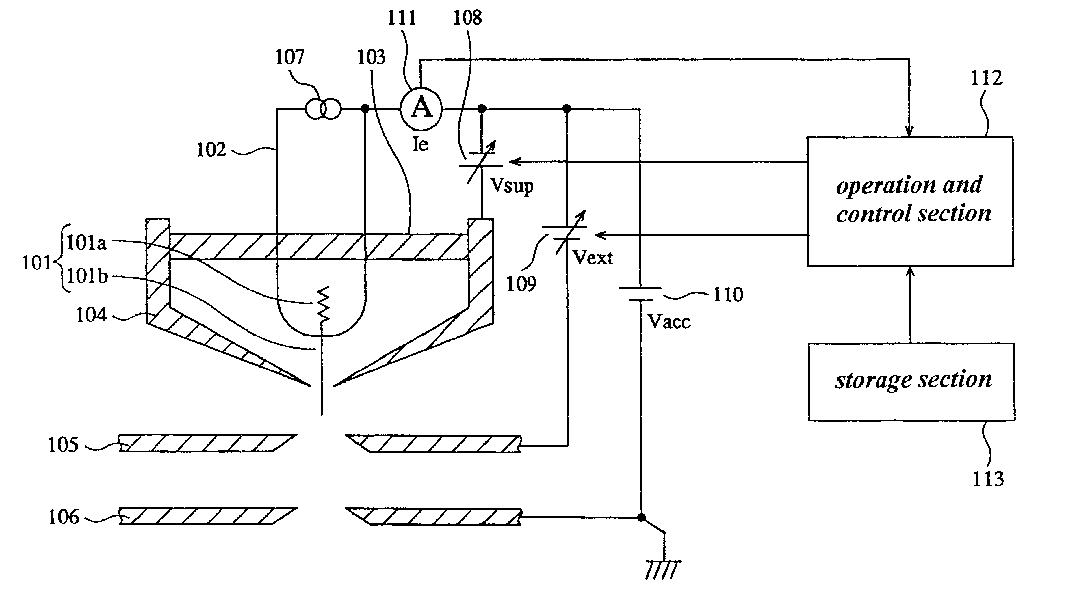
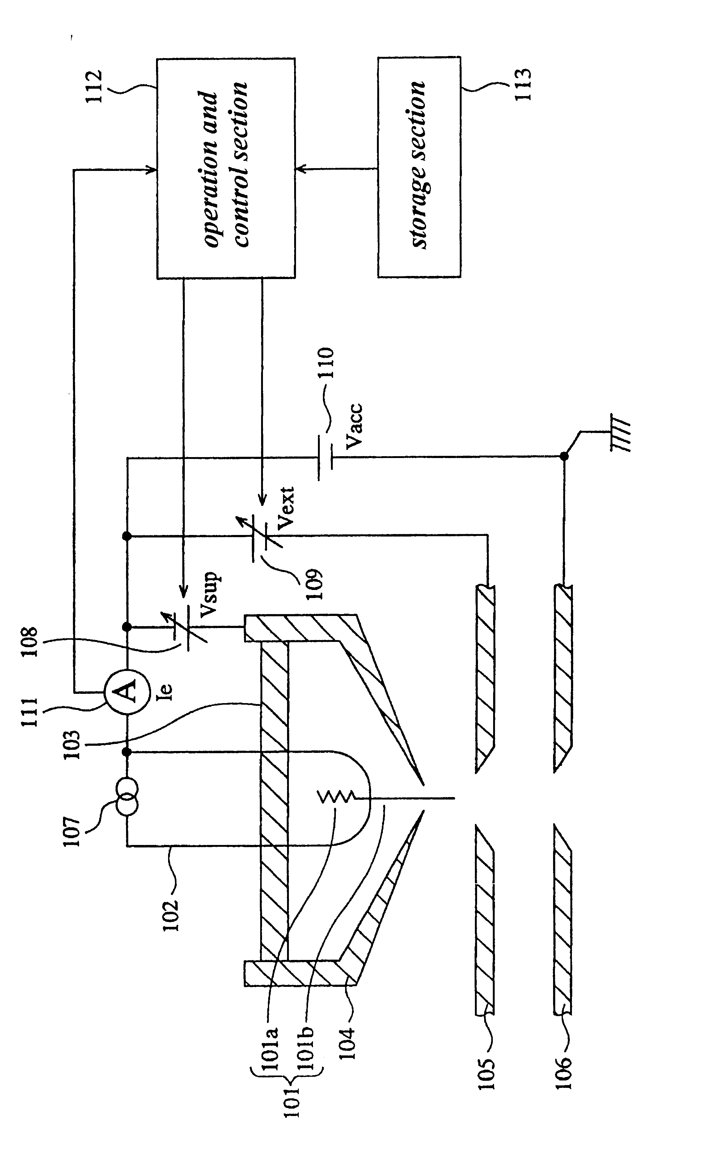
The FIGURE is a conceptual drawing showing the structure of a liquid metal ion source of this embodiment.

In the FIGURE, a needle 101 is provided with a coil shaped accumulating section 101a and a pointed emitter electrode 101b. The accumulating section 101a is used in order to hold a liquid metal, namely, a molten ion material (not shown in the drawings). A liquid metal film is formed on the surface of the emitter electrode lolb by liquid metal held on the accumulating section 101a flowing off. By generating a focused electric field at the tip of the emitter electrode 101b, metal ions are extracted from the liquid metal fil...


PUM


Abstract

A liquid metal ion source has an emitter electrode for emitting ions, an extraction electrode, proximate the emitter electrode for generating a focused electric field at a tip of the emitter electrode, and a suppression electrode proximate the extraction electrode for adjusting the strength of the focused electric field generated at the tip of the emitter electrode so that metal ions are extracted from liquid metal covering the tip of the emitter electrode at a desired emission current value. A storage device stores a function defining a relationship between variation (DELTAIe) in current of the emitter electrode and variation (DELTAVsup) in voltage of the suppression electrode as a function DELTAIe=F(DELTAVsup), with the voltage (Vext) of the extraction electrode being at a fixed value. A control apparatus controls voltages of the extraction and suppression electrodes and the emission current, detects the variation DELTAVsup in the voltage (Vsup) of the suppression electrode when a voltage (Vext) of the extraction electrode is made to vary by only DELTAVext with the current of the emitter electrode being held to a fixed value, and calculates flow impedance DELTAVext/DELTAIe using the voltage variation amounts DELTAVext and DELTAVsup and the function acquired form the storage device.

Description

1. Technical FieldThe present invention relates to a liquid metal ion source used, for example, in a focused ion beam system or the like, and more specifically to a liquid metal ion source provided with a function for detecting flow impedance.2. Related ArtConventionally, devices causing ejection of ions from a metal in a molten state are known, and utilize what is called a liquid metal ion source (or LMIS). The liquid metal ion source is used, for example, as an ion source for a focused ion beam (FIB) system. A focused ion beam system focuses metal ions using an ion-optical system, and irradiates a sample with ions. A focused ion beam system can be used, for example, in scanning ion microscope (SIM) observations, and can also perform deposition or etching of a thin film of any shape without using a mask.With a liquid metal ion source, the liquid metal is made to stick to the surface of a pointed emitter electrode, and metal ions are drawn out by causing a convergence field at the t...

Claims


Application Information

Patent Timeline
IPC IPC(8): H01J27/22H01J27/02H01J27/26G01R27/02H01J37/08H01J37/30
CPCH01J27/22H01J2237/0805H01J27/26
Inventor SUGIYAMA, YASUHIKOOI, MASAMICHI
Owner HITACHI HIGH TECH SCI CORP
Why Eureka
Try Eureka